Page 8 K&(%$*4.8"4,7%P'*#$"&8#J%/7*,#*%4,77%QRSSSRSTTRUVWV1 ITEM 62879
F=K6EB CX6I=E@C> D=@>E6>=><6F6E;X
K'*7%E,8]%F*$'/%@8#$('4$"&8#
Y=I>@>Z\ Fuel tank (not included) must be
CARB compliant and designed specifically for
containing gasoline or voids warranty. The tank
must be mounted to a stable mounting frame.
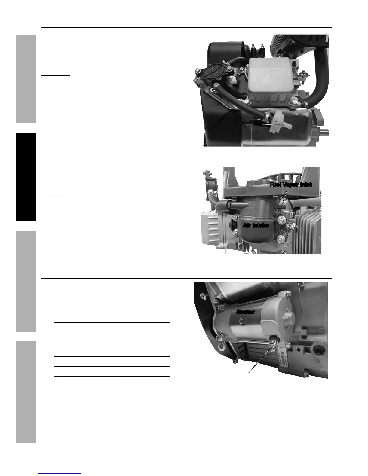
1. Connect a fuel hose (not included) from the
fuel tank to the Fuel Hose Connector, and
secure it in place with a hose clamp. See
Figure F. If possible, incorporate a fuel shutoff
valve (not included) on the fuel hose.
2. Connect a hose to the Fuel Vapor
Inlet on the Air Intake to contain
gasoline vapors. See Figure G.
Y=I>@>Z\ The end user is responsible for
complying with all applicable CARB and EPA
evaporative emissions requirements for the
fuel system. Some areas may have specific
gasoline vapor containment requirements;
comply with local, state, and federal laws.
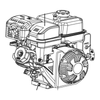
K'*7%O&#*%
<&88*4$&(
K"3'(*%K-%%K'*7%O&#*%<&88*4$&(
="(%@8$,]*
K'*7%!,/&(%@87*$
K"3'(*%Z-%%K'*7%!,/&(%@87*$
[,$$*(H%F*$'/%@8#$('4$"&8#
1. Equipment should include a fully charged, lead-
acid 12 volt, 36 Ah battery (not included)
2. To connect equipment solenoid to Engine
Starter, only use cables sized to match
their length according to Table A.
<,+7*%Z,'3*%%
d7&)*(%3,'3*%8'5+*(#%
5*,8%$."4]*(%4,+7*#e
D,G"5'5%
<,+7*%A*83$.
T 5′
f 7′
g 12′
E,+7*%=-%%%D"8"5'5%<,+7*%L",5*$*(#
3. Attach the positive cable from the positive
battery terminal to the outer terminal on the
Starter. Connect cable securely to prevent
disconnection and short circuits. See Figure H.
F$,($*(
X&#"$"M*
K"3'(*%O
4. Connect the negative cable securely to one of the
engine mounting bolts. Connect cable securely
to prevent disconnection and short circuits.
5. Coat the terminals and cable ends with
a corrosion-preventive coating.