Page 8 For technical questions, please call 1-888-866-5797. ITEM 59190
SAFETY SETUP OPERATION MAINTENANCE
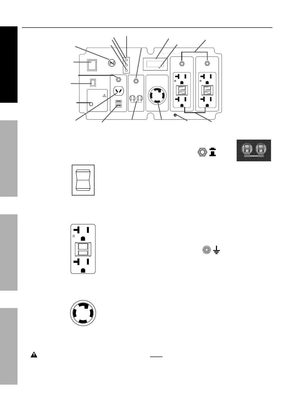
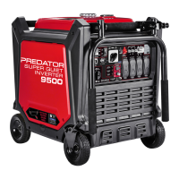
Components and Controls (continued)
The following are descriptions of the controls
on the power panel. Your Generator has
sockets to power your products with circuit
breakers to protect the voltage flow.
1.
I
O
START
Engine Switch: Used to start and stop the Engine.
2. AC Receptacles: The Generator contains several
AC Receptacles to power tools and equipment.
a.
RESET
TEST
RESET
TEST
3-Prong, duplex
120 volt GFCI receptacle
(NEMA #5-20)
b. 4-Prong, twistlock,
120/240 volt receptacle
(NEMA #L14-30)
WARNING! TO PREVENT SERIOUS INJURY:
Connect tools and equipment only to the Receptacle
(120 volt or 240 volt) that is compatible with the
electrical characteristics and rated capacities
of the tools and equipment being used.
3.
ON
OFF
Circuit Breakers: The circuit
breaker protects the Generator from overloading.
The rating of the breaker and the load it protects are
marked near the breaker. Should any of the Circuit
Breakers trip, the Generator will stop the electricity
output. If this happens, unplug all loads from the
Generator. Then, turn the tripped Circuit Breaker to
ON and re-attach loads gradually. Note: For push-
type Circuit Breakers allow a few minutes for cool-
down before resetting.
4. 12 VDC Receptacle: 12 VDC Receptacle
provides a power source for 12 volt DC items.
5. Grounding Terminal: Prior to each use, set
up the ground wire (not included) connection to
the Grounding Terminal to properly ground the
Generator. Refer to Grounding on page 10
for instructions on grounding the Generator.
6. Digital Display: Press the Mode Button to
cycle through the Display’s functions:
• Voltage
(Displays U + voltage reading. Example: “U120”)
• Frequency
(Displays F + frequency reading. Ex.: “F60”)
• Current session runtime
• Total (accumulated) runtime
Note: Every 50 hours, a blinking maintenance
reminder will appear on the screen (P050, P100,
P150, etc.) See Page 18 for maintenance
schedule. To clear a maintenance reminder, press
and hold the Mode Button for 5 seconds.
Mode Button
#5-20R GFCI
Receptacles
L14-30
Receptacle
20A Breakers
Digital Display
Ground
Indicators
Output
Overload
Low Oil
30A Breaker
CO Sensor
Light
ESC
Throttle
Start
Switch
Choke
DC Breaker
AC Overload
Reset
12V DC
Receptacle
USB Ports