1-20 Disassembly Procedures
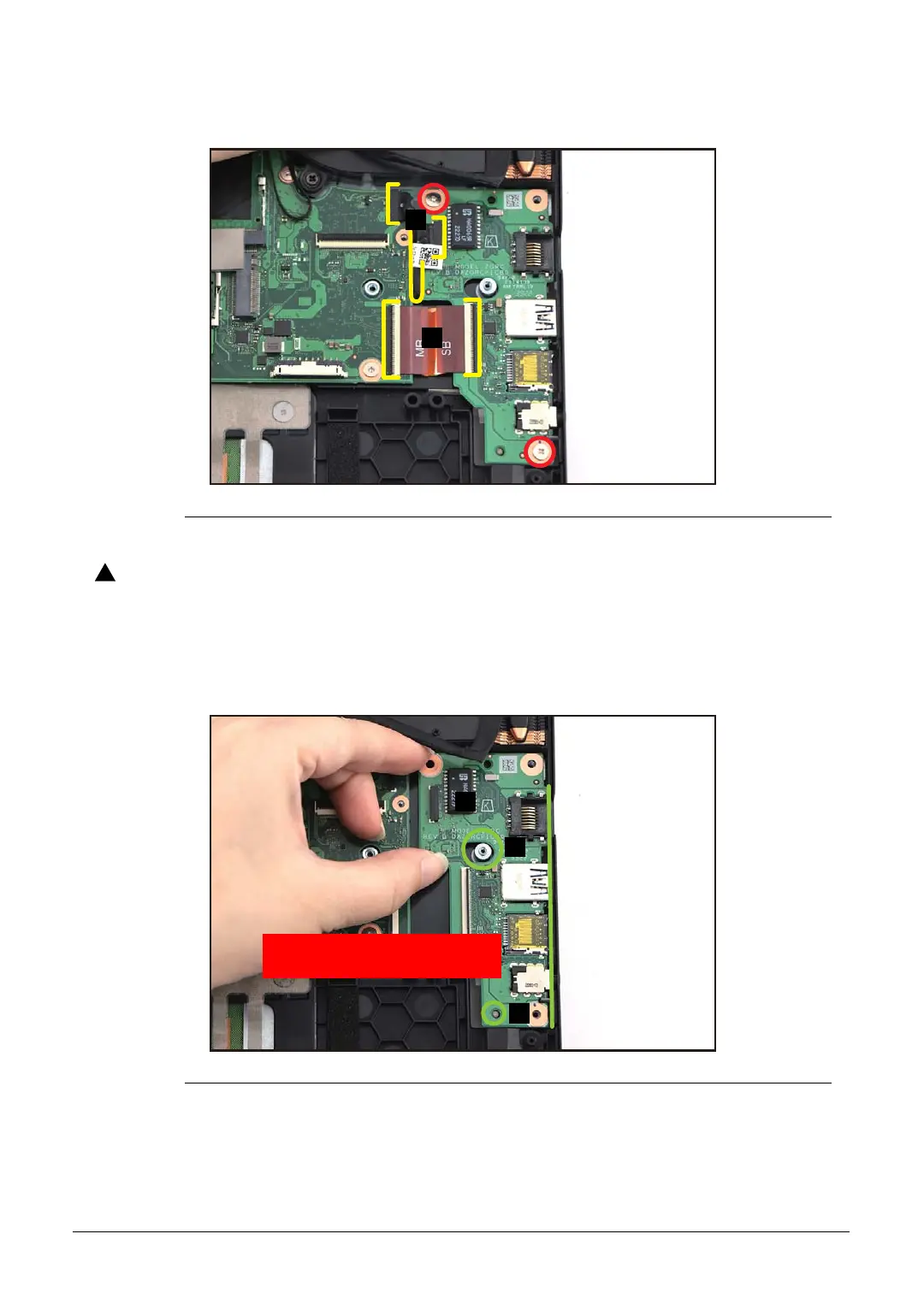
4. Remove two (2) screws securing the USB board (Figure 1-24).
Figure 1-24. USB Board Removal
USB board FPC (Flexible Printed Circuit) can be damaged if removed while
the mainboard and USB board connectors are locked.
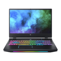
5. Release the USB board (D) from the I/O port slots and guide pins (E) on the top
assembly (Figure 1-25). Then remove the USB board.
Figure 1-25. USB Board Removal
D
E
WEEE Annex VII Component:
USB Board
E