1-22 Disassembly Procedures
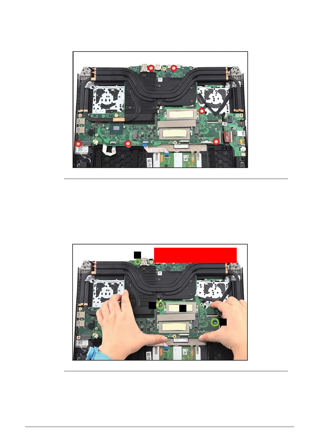
6. Remove six (6) screws securing the mainboard (Figure 1-27).
Figure 1-27. Mainboard Removal
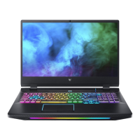
7. Lift to release the mainboard with the heatsink (F) from the guide pins (G) on the top
assembly but DO NOT remove yet! (Figure 1-28).
Make sure to remove the mainboard with the heatsink vertically
upwards.
Figure 1-28. Mainboard Removal
F
G
G
G
WEEE Annex VII Component:
Mainboard