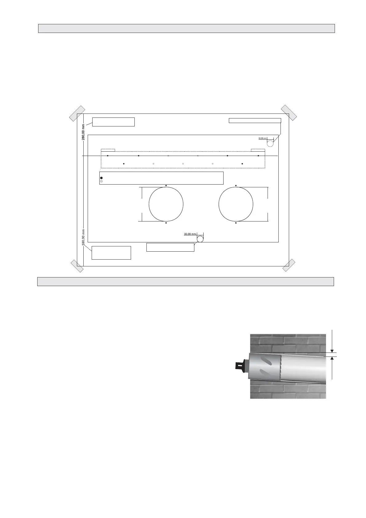
2.2 PAPER TEMPLATE
Paper Template (copy to scale enclosed with accessories)
rilling the hole above ground floor level, please ensure that an area has
been secured and while the holes are drilled the outside area is supervised, until drilling has been
completed.
INTAKE AND OUTLET HOLES
DRAINAGE HOLE
Fasten the template to the wall once the following guidelines have been thoroughly checked.
Do not drill any holes until you are 100% confident that there are no obstacles in the area you wish to drill
and there are no obstructions, which could be hidden by the construction of the wall, for example:
Electrical wiring water & gas pipes or supporting lintels or beams.
Ensure that a sprit level is used, as the unit must be level.
Follow the installation instructions & measurements in full.
This operation should be carried out using the proper tools (diamond tip
or core borers drills with high twisting torque and adjustable rotation speed).
Fasten the template to the wall taking care to check the distance
From the floor and or ceiling and keep it horizontal by using a spirit level.
Use a pilot drill to mark the centre of each core hole to be drilled.
Use a core boring head having a diameter of 165 mm to
drill the two holes for intake and outlet the air.
It is recommended that the holes must have a slightly downward
inclination of 3-5 degrees to prevent any backflow of water from the pipes.
The unit produces condensate that has to be extracted to enable the unit to operate correctly. It is necessary
to drill a hole through the wall measuring 30mm in diameter in the position shown in the paper template.
Drainage occurs by gravity. For this reason, it is essential for the drain line to have a minimum downward
inclination of at least 3% throughout its length.
!
!
!
!
!
!
!
2.3 DRILLING THE WALL
Please note: If you are d
8
HOT AIR
DISCHARGE
HOLE
AIR
INTAKE
HOLE
DRAINAGE HOLE
MINIMUM DISTANCE
FROM FLOOR
SIZE OF THE BRACKET
OBLIGATORY FIXING POINTS
EXTRA FIXING POINTS TO USE IF THE WALL IS NOT SOLID
MINIMUM DISTANCE
FROM CEILING
ELECTRICAL WIRING HOLE
165 mm
165 mm