PAGE
6
2.4 Installing the unit
Installation
GUIDE
Tools required
• Phillips #2 or Robertson #1
screwdriver
• 3/32” drill bit
• Tin snips or metal shear
• Power Drill
Location
Return side connections is to be installed
after the last branch on the return air
plenum and minimum 2 linear ft distance
from furnace.
A 5-ft power cord is supplied with the
unit. If not available a 120VAC outlet
needs to be supplied.
Note:
Refer to the Owner’s Operation Guide
(p.9) for details on how to remove the
unit’s door and filters
Step by step Installation
Steps involved in the preparation of the plenum mount system are
as followed:
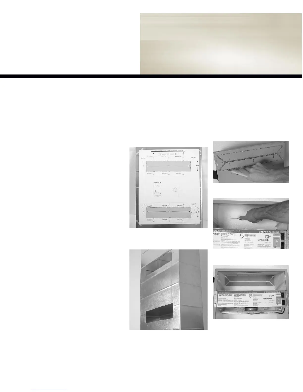
figure 2.2b
-One cut permits the clean
removal of the insulation piece.
Step 2:
Preparing ducting flairs
Remove the door and filters and proceed to
cut the insulation as illustrated below.
figure 2.2a -
Cut the insulation along the inside
edge of both inlet and outlet ports to remove
the insulation from the port openings.
Step 1:
Preparing return air plenum
Find a location that satisfies both service and
maintenance requirements and proceed to cut
holes as illustrated below.
figure 2.1a -
Tape template to return air
plenum. Cut opening with metal shears and
predrill for the securing screws.
figure 2.1b -
Remove template.
figure 2.2c
-The unit should look like this
when the foam piece is removed.