2.4 Installing the unit (Continued)
PAGE
8
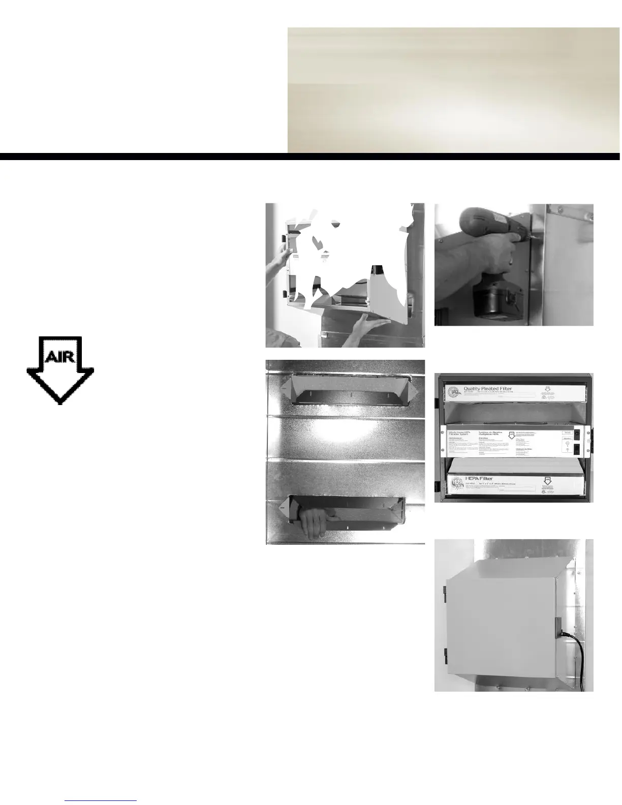
Step 3:
Mount Hepa
Step 3: (Continued)
Installation
GUIDE
figure 2.3b -
Unfold the ducting flairs
co m ple tly to sandwich the return air plenum
between the ducting flair and the filtration unit.
figure2.3a -
Align unit into place.
figure 2.3c -
Install unit as usual using all
supplied fastening hardware.
Step 4:
Finishing
Tips
to installer
It is recommended that the filtration unit have
a devoted receptacle with 115V. It is not rec-
ommended to connect unit with an extension
cord. If no receptacle is available please call
an electrical contractor to have one installed.
MAKE SURE TO INSTALL
FILTER ACCORDING TO
AIR FLOW DIRECTION FOR
MAXIMUM PERFORMANCE
Check for this symbol on each
filters and it is located on the
unit’s motor plate.
figure 2.4b -
Replace door and insert power
cord into the receptacle of the filter units and
the other end into wall outlet.
Stage 1&2: Pre-Filter & Carbon
Stage 3: HEPA Filter
figure 2.4a -
Remove protective plastic covers
from all filters and replace them in their prop-
er location (Stage 1, 2 and 3).