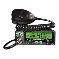
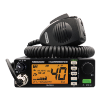
Do you have a question about the PRESIDENT Jack and is the answer not in the manual?
Lists necessary test equipment for PLL and carrier oscillator alignment procedures.
Step-by-step instructions for aligning the PLL and carrier oscillator.
Diagram illustrating the connection of test equipment for alignment.
Lists necessary test equipment for transmitter portion alignment procedures.
Step-by-step instructions for aligning the transmitter portion.
Diagram illustrating the connection of test equipment for transmitter alignment.
Lists necessary test equipment for receiver portion alignment procedures.
Step-by-step instructions for aligning the receiver portion.
Diagram illustrating the connection of test equipment for receiver alignment.
Wiring diagram for a 6-pin microphone connector (NC 518).
Wiring diagram for a 4-pin microphone connector (NC 514).
| Modulation Modes | AM / FM |
|---|---|
| Channels | 40 |
| Antenna Impedance | 50 ohms |
| Frequency Range | 26.965 - 27.405 MHz |
| Output Power | 4 W |
| Type | Mobile CB Radio |
