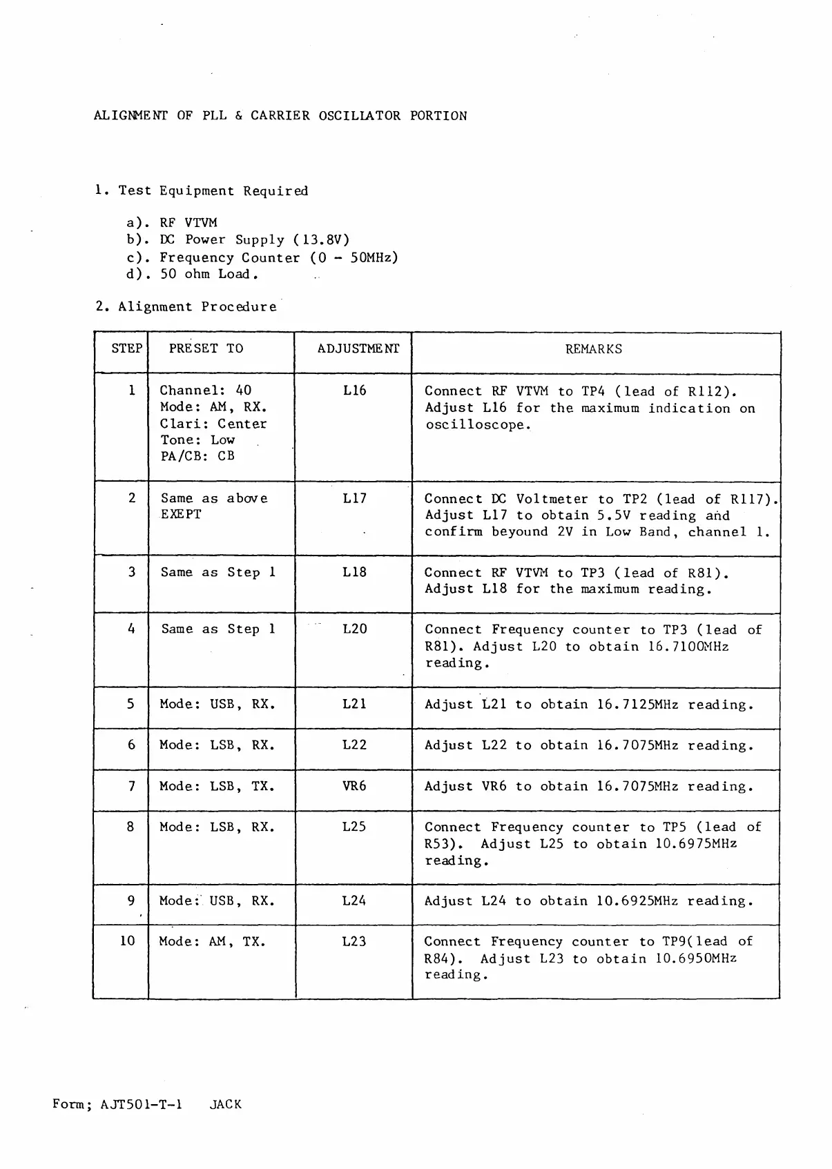
ALIGNMENT OF PLL & CARRIER OSCILLATOR PORTION
1. Test Equipment Required
a) . RF VTVM
b) . DC Power Supply (13.8V)
c) . Frequency Counter (0 - 50MHz)
d) . 50 ohm Load.
2. Alignment Procedure
STEP PRESET ТО ADJUSTMENT
REMARKS
1
Channel: 40
Mode: AM, RX.
Clari: Center
Tone : Low
PA/СВ: CB
L16
Connect RF VTVM to TP4 (lead of R112).
Adjust L16 for the maximum indication on
oscilloscope.
2
Same as above
EXE PT
L17
Connect DC Voltmeter to TP2 (lead of R117).
Adjust L17 to obtain 5.5V reading and
confirm beyound 2V in Low Band, channel 1.
3
Same as Step 1
L18
Connect RF VTVM to TP3 (lead of R81).
Adjust L18 for the maximum reading.
4
Same as Step 1
L20
Connect Frequency counter to TP3 (lead of
R81). Adjust L20 to obtain 16.7100MHz
reading.
5
Mode: USB, RX. L21
Adjust L21 to obtain 16.7125MHz reading.
6
Mode: LSB, RX.
L22 Adjust L22 to obtain 16.7075MHz reading.
7
Mode: LSB, TX.
VR6
Adjust VR6 to obtain 16.7075MHz reading.
8
Mode: LSB, RX.
L25 Connect Frequency counter to TP5 (lead of
R53). Adjust L25 to obtain 10.6975MHz
reading.
9
Mode: USB, RX.
L24
Adjust L24 to obtain 10.6925MHz reading.
10
Mode: AM, TX. L23
Connect Frequency counter to TP9(lead of
R84). Adjust L23 to obtain 10.6950MHz
reading.
Form; A J T 501-T -1 JACK
 Loading...