6 Travel Scooter Series
*Charger Power Cord Receptacle (Tiller Port) also functions as a Programming Port in Tiller Consoles E and F (see fi gures 5 and 6).
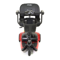
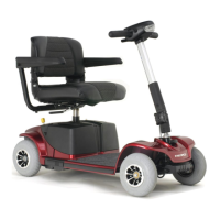
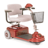
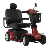
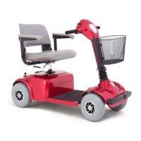
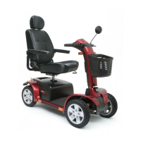
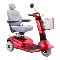
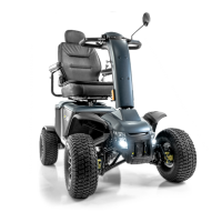
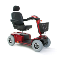
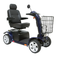
II. YOUR TRAVEL SCOOTER
1 2 3 4
5
1 4 3 2
5
6
7
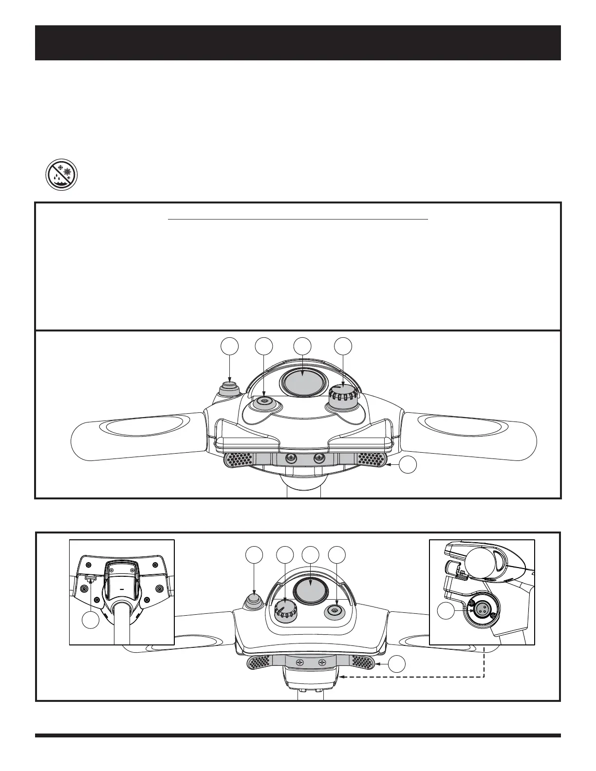
Figure 1. Tiller Console A (Models 36, 40X, 44E)
Figure 2. Tiller Console B (Models 39, 40E, 44E, 49, 83, 84)
TILLER CONSOLE
The tiller console houses all controls needed to drive your Travel Scooter, including the key switch, throttle
control lever, horn button, speed adjustment dial, and the battery condition meter. Please refer to the Travel
Scooter Features Table on the inside of the front cover of this owner’s manual to determine which console fi gure
to choose. See fi gures 1 through 6.
PROHIBITED! Do not expose the t ille r console to moist ure. In the eve nt that the t ille r c onsole
does bec om e ex posed to moist ure, do not attempt t o ope rate your Travel Scooter unt il t he tiller
console ha s drie d t horoughly.
IDENTIFICATION KEY FOR FIGURES 1 THROUGH 6
1. Horn
2. Key Switch
3. Battery Condition Meter
4. Speed Adjustment Dial
5. Throttle Control Lever
6. Charger Power Cord Receptacle
(Tiller Port)*
7. Off-board Charger Fuse
8. Light Fuse
9. Light Switch
10. USB Charger Port
11. Hi-Lo Switch