Jazzy Select Elite www.pridemobility.com 19
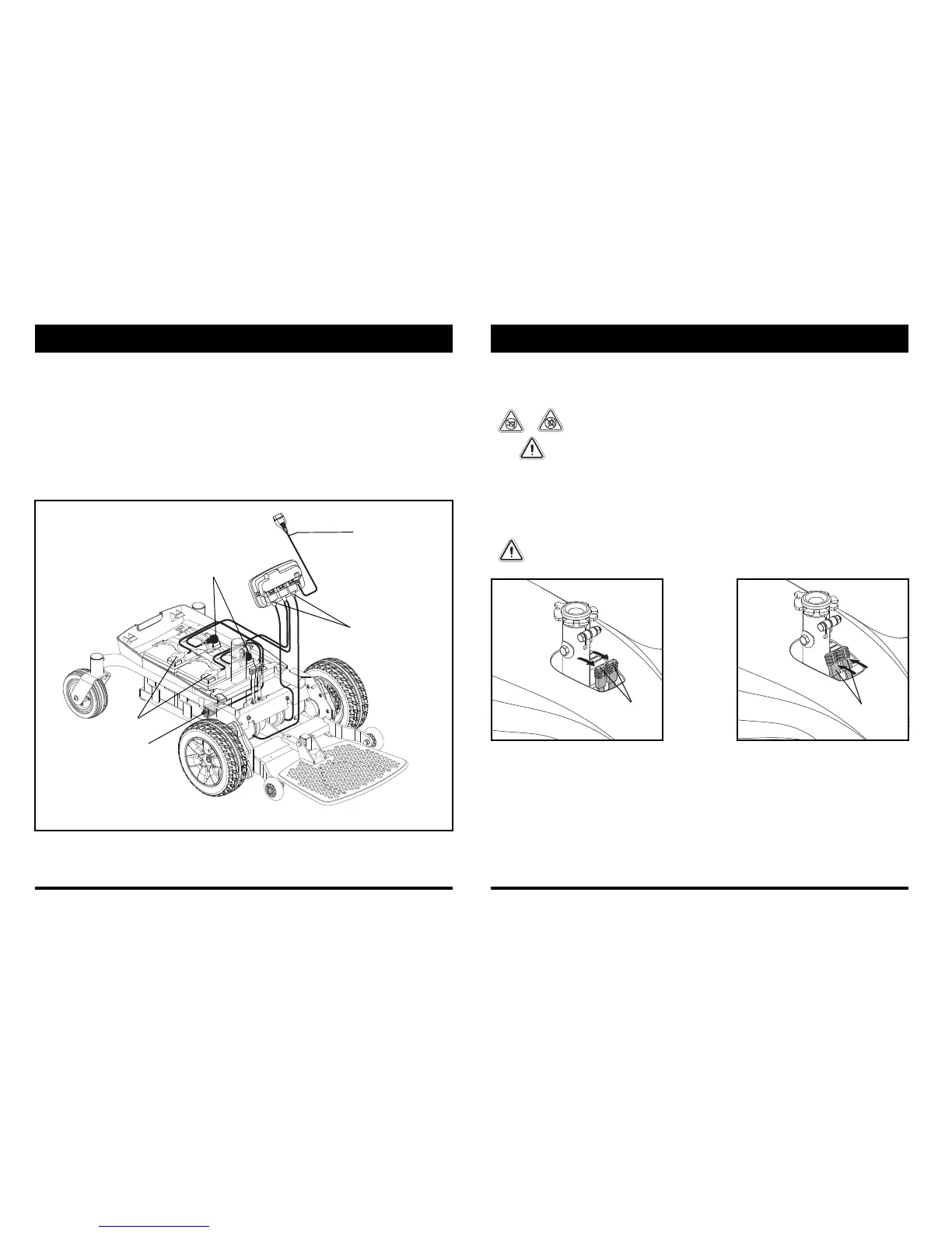
Figure 7. Jazzy Select Elite Electrical Components
III. YOUR POWER CHAIR
Electrical Components
The electrical components are located either on or inside the power base. The main circuit breaker is located on
the side of the power base. The power module is located under the front cover. See figure 7.
Main Circuit Breaker: The main circuit breaker is a safety feature built into your power chair. When the batteries
and the motors are heavily strained (e.g., from excessive loads), the main circuit breaker trips to prevent damage
to the motors and the electronics. If the circuit trips, allow your power chair to “rest” for approximately one
minute. Next, push in the circuit breaker button, turn on the controller, and continue normal operation. If the main
circuit breaker continues to trip repeatedly, contact your authorized Pride Provider.
Power Module: Provides connection between the controller and the motors and batteries.
CONTROLLER HARNESS
MOTOR CONNECTORS
BATTERY CONNECTORS
MAIN CIRCUIT BREAKER
BATTERY CONNECTORS
20 www.pridemobility.com Jazzy Select Elite
Manual Freewheel Levers
Your power chair has a manual freewheel lever on each motor. Manual freewheel levers enable you to disengage
the drive motors from the gearboxes and maneuver the chair manually.
WARNING! Do not use the power chair while the drive motors are disengaged! Do not
disengage the drive motors when the power chair is on an incline or decline, as the
unit could roll on its own. Only engage the freewheel mode when on a level surface.
WARNING! It is important to remember that when your power chair is in freewheel
mode, the braking system is disengaged.
To engage or disengage the drive motors:
1. Locate the lever on the top of the power base.
2.
Push both levers forward away from the seat post to engage the drive motors (drive mode).
See figure 8.
3. Pull both levers rearward toward the seat post to disengage the drive motors (freewheel mode). See figure 9.
If a lever is difficult to move in either direction, slightly rock the power chair back and forth. The lever should
then move to the desired position.
WARNING! Do not use the freewheel lever handles as tie-down points to secure this product.