Jazzy Select Elite www.pridemobility.com 21
Seat Installation
It may be necessary to install the seat either prior
to initial operation or after transporting your
power chair.
WARNING! Do not pick up the seat
frame by the armrests. They are
free to pivot, and you may lose
control of the seat if they do so.
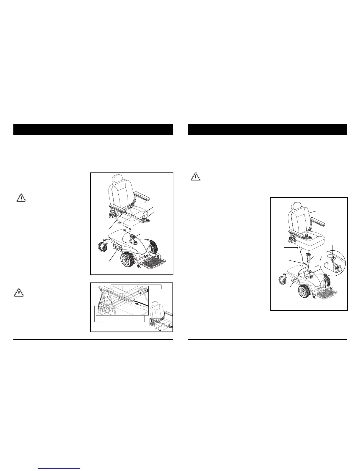
To install the seat:
1. Adjust the upper seat post to the desired
position and insert the bolt through the seat
post and secure with the nut. See figure 10.
2. Slide the seat down onto the upper seat post.
See figure 10.
3. Install the controller into one of the armrests.
Tighten the setscrew with the supplied hex
key. See figure 10.
4. Lift the armrest straight up, then route the
controller harness and secure with wire ties as
shown in figures 10 and 11.
NOTE: It is important that the armrest be lifted
straight up prior to securing the controller
harness with wire ties.
MANDATORY! Prevent controller
harness damage! Avoid routing
the controller harness on the
outside of the armrest pad. Route
the harness under the armrest or
toward the inside of the armrest
pad. Use correct tie-down points
for the controller harness to
prevent the harness from getting
caught in the drive tires, pinched
in the seat frame, or damaged
when passing through doorways.
5. Plug the controller harness into the connector
on the power base. See figure 6.
IV. ASSEMBLY
INITIAL ASSEMBLY
Your power chair may require some assembly either before initial use or after transportation.
NOTE: Any nylon insert lock nut removed during the disassembly or adjustment of the power chair must be
replaced with a new nylon insert lock nut. Nylon insert lock nuts should not be reused as it may cause damage
to the nylon insert, resulting in a less secure fit. Replacement nylon insert lock nuts are available at local
hardware stores or by contacting your authorized Pride Provider.
Figure 10. Seat and Controller Assembly
SEAT
CONTROLLER
POWER BASE
Figure 11. Controller Harness Routing
SETSCREW
WIRE TIES
WIRE TIES
LOWER SEAT
POST
22 www.pridemobility.com Jazzy Select Elite
COMFORT ADJUSTMENTS
After becoming familiar with your power chair’s operation, you may find the need to make some adjustments to
increase your comfort, such as seat height, armrest angle, foot platform angle, and controller position. Refer to the
following information before making comfort adjustments.
WARNING! The center of gravity of your power chair was factory set to a position that meets the
needs of the demographic majority of users. Your authorized Pride Provider has evaluated your
power chair and made any necessary adjustments to suit your specific requirements. Do not
change your seating configuration without first contacting Pride Mobility Products or your
authorized Pride Provider.
WARNING! Some power chair components are heavy. You may need assistance to lift or carry
them. Please refer to the specifcation table for specific component weights before you
disassemble the power chair.
WARNING! Remove the occupant from the power chair before making any adjustments.
V. COMFORT ADJUSTMENTS
Figure 12. Seat Height Adjustment
You may need the following to make comfort
adjustments:
metric/standard socket set and ratchet
adjustable wrench
metric/standard hex key set
thread lock
Seat Height Adjustment
You can change the seat height to one of three positions
in 1-in. (2.5-cm) increments.
To remove the seat:
1. Turn off the power to the controller.
2. Ensure the power chair is in drive mode. See figure 8.
3. Disconnect the controller connector from the
power base. See figure 12.
4. Disengage the seat release lever. See figure 12.
5. Swivel the seat left or right and then pull it up and
off of the power base.
To change the seat height:
1. Turn off the power to the controller.
2. Ensure the power chair is in drive mode.
See figure 8.
3. Disconnect the controller connector form the
power base. See figure 12.
4. Remove the seat from the power base.
5. Loosen the hardware at the rear of the seat post. See
figure 12.
6. Remove the seat height adjustment bolt, washers,
and nuts from the seat post. See figure 12.
7. Raise or lower the upper seat post to the desired
position.
8. Reinstall the seat height adjustment hardware to the
seat post.
9. Tighten the hardware at the rear of the seat post.
10. Reinstall the seat.
11. Reconnect the controller to the power base.
NOTE: To rotate the seat, use the seat release lever
located under the seat.
SEAT
RELEASE
LEVER