34-50 04/02/2010
17
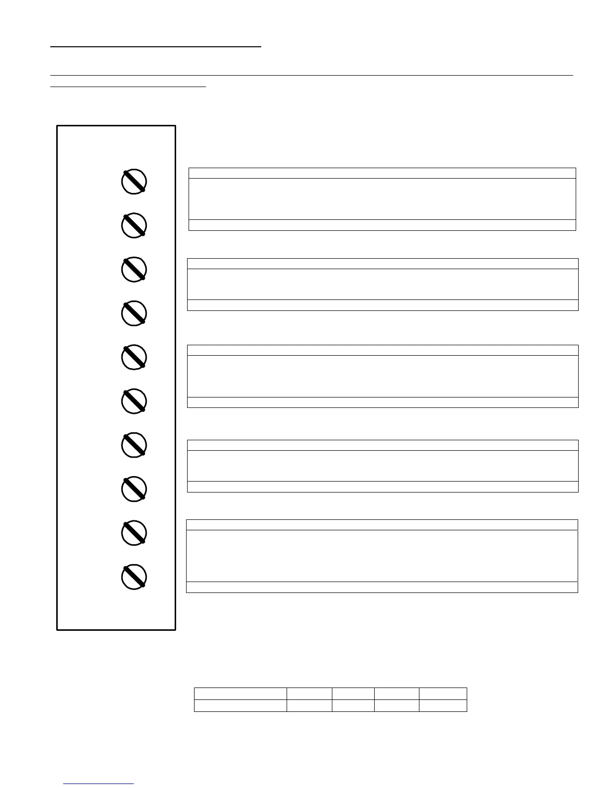
REMOTE CONNECTIONS - TERMINAL STRIP
A terminal strip for the remote connection is located behind the control panel and is accessed by removing the top pan.
Terminals A1-A2 and P1-P2 are functional only when the PRIMERA
®
is equipped with the factory installed option
required to activate the terminals. Terminals R1-R2, C1-C2 and T1-T2 are standard pre-wired functions on all
PRIMERA
®
products. The following describes the functions of each of these terminals and the factory-installed options
required to activate the terminals. Disconnect electrical power before accessing the terminal strip.
R1-R2. Used to activate /de-activate boiler from remote master control. *
Terminals are wired to a relay in a remote Boiler Management or Energy
Management System. When relay closes, circuit from R1 to R2 is completed and boiler
controls are enabled. Boiler ships from factory with jumper between terminals Remove jumper
when connecting to a remote boiler controller.
Options required: none (see note)
P1-P2: Activates remote equipment and requires confirmation signal back to boiler
Provides a maximum 10 amp relay contact closure to activate a remote device, such as
mechanical room air louvers, draft inducer or power venter. The remote device must send
return signal via proving switch to confirming proper operation to terminals C1-C2, prior to
boiler being able to energize.
Options required: Option 20 (supplies relay)
C1-C2: Used for proving operation of remote device.
Terminals are wired to a proving switch on a remote device such as a power venter. When
relay closes, circuit from C1 to C2 is completed and boiler controls are enabled. Boiler ships
form the factory with jumper between terminals.
Options required: None (see note)
T1-T2: Used for external 2-stage or modulation control *
To connect external control to a two-stage PRIMERA, remove the factory installed jumper
connecting terminals T1-T2, then connect the external control signal to terminals T1 and T2. To
connect external control to a modulating PRIMERA, disconnect and cap the blue wire
connected to terminal T2 and connect the external modulating signal to terminals T1 (positive)
and T2 (negative).
Options required: None.
* For detailed information on connecting PRIMERA
®
to a multiple boiler controller, refer
to supplemental installation manual number 34-400.5. This document is available on-
line at www.riversidehydronics.com.
Note: Do not use single strand bell wire for remote field connections to terminals R1-R2 and C1-C2. Use only
multi-strand copper wire. See table below for wire length and gauge:
A1-A2: Used to activate a remote alarm signaling shutdown of combustion control
Provides a maximum 10 amp relay contact closure when flame safeguard terminates
combustion due to tripping any of the following: air proving switch, high limit switch, low water
flow switch or flame sensor.
Options required: Option 23 (supplies relay)
Wire Gauge 18 GA 16GA 14 GA 12 GA
Maximum Length 30 FT 50 FT 75 FT 100 FT
R1
T2
T1
C2
C1
P2
P1
A2
A1
R2