34-50 04/02/2010
5
CLEARANCES TO COMBUSTIBLE SURFACES
The appliance must not be installed on a combustible floor, on carpet, on other combustible floor coverings or on a
non-combustible floor covering combustible material. Minimum 1” clearance must be provided from any appliance or
venting surface to adjacent combustible construction.
ELECTRICAL REQUIREMENTS
This appliance is wired for 120-volt service. The appliance, when installed, must be electrically grounded in accordance with
the requirements of the authority having jurisdiction or in the absence of such requirements, with the latest edition of the
National Electrical Code ANSI/NFPA No. 70. When the unit is installed in Canada, it must conform to the CAE C22.1,
Canadian Electrical Code, Part 1 and/or Local Electrical Codes.
1. All wiring between the unit and field installed devices must be made with type T wire.
2. Line voltage wire exterior to the appliance must be enclosed in approved conduit or approved metal clad cable.
3. The appliance pump must be controlled by the provided intermittent pump control relay.
4. To avoid serious damage, DO NOT energize the unit until the system is full and water is flowing through the unit.
COMBUSTION AND VENTILATION AIR
Provisions for adequate combustion and ventilation air to the mechanical room must be in accordance with Section
5.3, Air for Combustion and Ventilation of the latest edition of the National Fuel Gas Code, ANSI Z223.1 and/or
CAN/CSA B149, Installation Codes or applicable provisions of the local building codes.
Equipment located in confined spaces requires two openings installed within 12” (300 m) from the top and bottom of
the room to assure adequate combustion air and proper ventilation. The total input of all gas utilization equipment
installed in the room must be used to determine the required minimum air volume needed for combustion, ventilation
and dilution of flue gasses.
1. All Air From Outdoors:
a. Each opening requires a minimum free area of 1 square inch
per 4000 Btu/hr input if directly communicating
with the outdoors or communicating to the outdoors through vertical ducts.
b. Each opening requires a minimum free area of 1 square inch
per 2000 Btu/hr input if communicating with the
outdoors through horizontal ducts.
2. All Air From Inside The Building:
Each opening requires a minimum free area of 1 square inch
per 1000 Btu/hr input, but not less than 100 square
inches (0.06 m
2)
.
3. Combination Of Air From The Indoors And From The Outdoors:
Refer to National Fuel Gas Code, ANSI Z223.1 and/or CAN/CSA B149, Installation Codes or applicable provisions
of the local building codes.
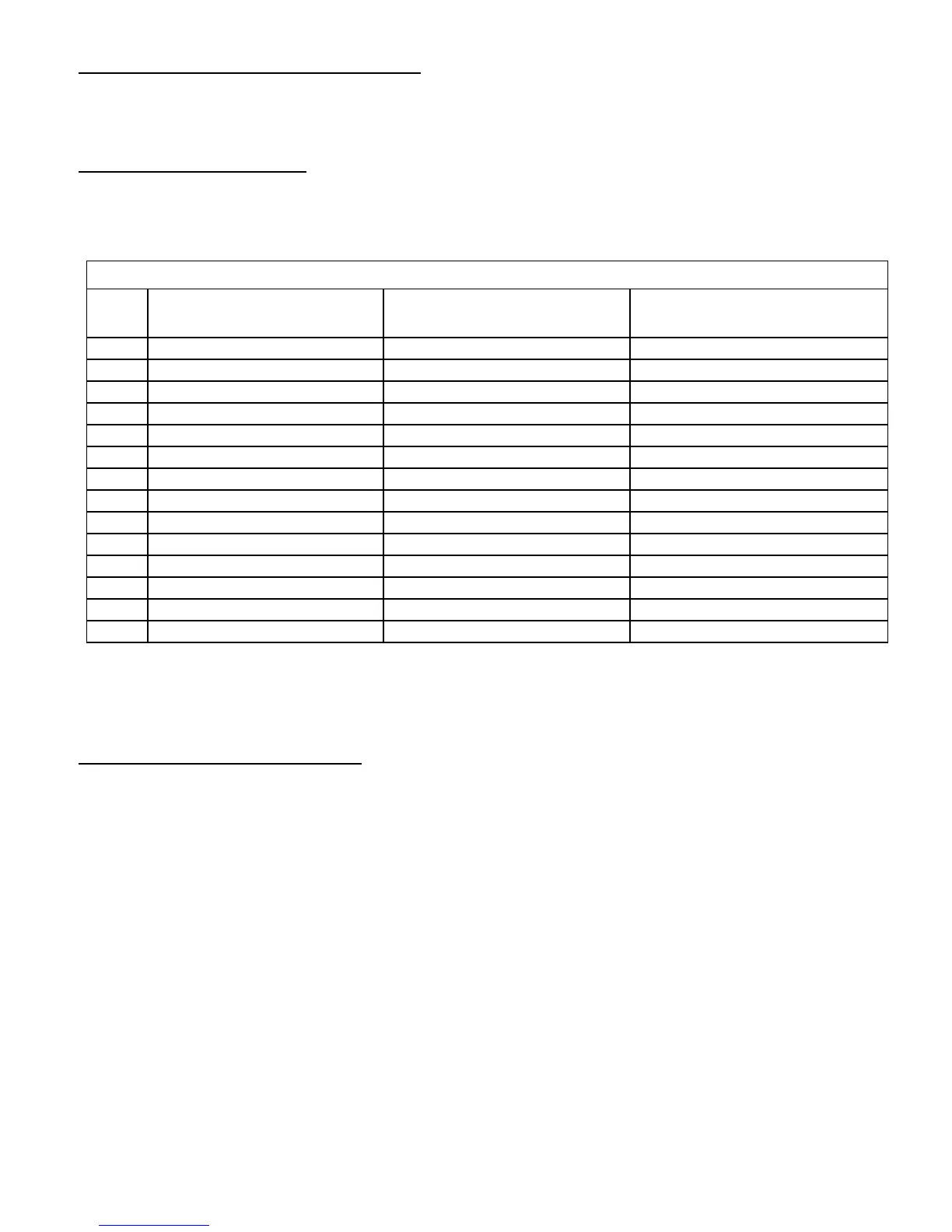
AMPERAGE DRAW
Model
Total Amps @120VAC
(Includes Water Heater Pump Amp Draw.
Does not include optional boiler pump.)
Appliance Amp Draw @120VAC
(Does Not Include Pump Amp Draw)
Standard Pump Amp Draw @120VAC
(Amp draw for alternate pumps may differ)
400B Approximately 4 Approximately 4 Approximately 2.1 (pump optional)
400W Approximately 6.1 Approximately 4 Approximately 2.1
540B Approximately 6 Approximately 6 Approximately 2.1 (pump optional)
540W Approximately 8.1 Approximately 6 Approximately 2.1
750B Approximately 10 Approximately 10 Approximately 8.2 (pump optional)
750W Approximately 18.2 Approximately 10 Approximately 8.2
1000B Approximately 10 Approximately 10 Approximately 8.2 (pump optional)
1000W Approximately 18.2 Approximately 10 Approximately 8.2
1200B Approximately 10 Approximately 10 Approximately 8.2 (pump optional)
1200W Approximately 18.2 Approximately 10 Approximately 8.2
1600B Approximately 10 Approximately 10 Approximately 8.2 (pump optional)
1600W Approximately 18.2 Approximately 10 Approximately 8.2
2000B Approximately 12 Approximately 12 Approximately 11.2 (pump optional)
2000W Approximately 23.2 Approximately 12 Approximately 11.2