34-50 04/02/2010
25
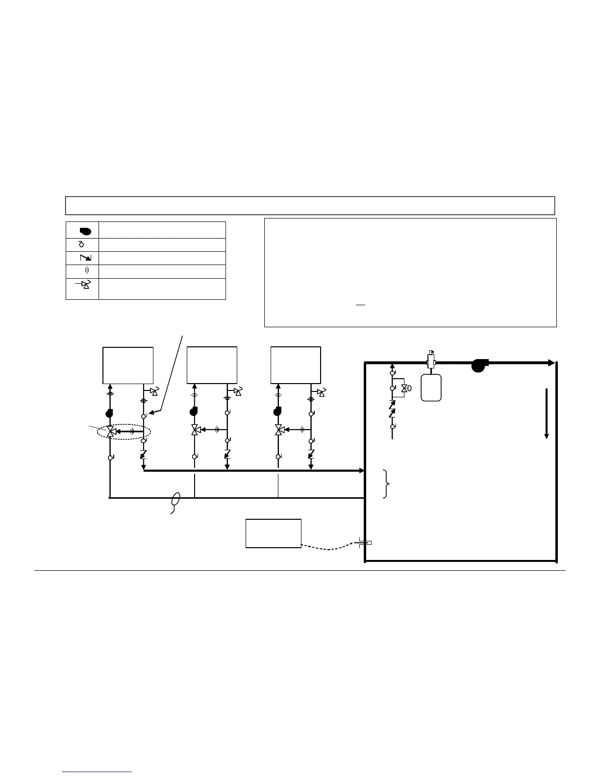
Piping Schematic for Multiple PRIMERA® Boilers - Primary-Secondary
Circulator (confirm proper sizing)
Full Port Isolation Ball Valve
Swing Check Valve
Union
Pressure relief valve. Pipe to drain with
no restrictions or valves.
Building Return
Notes:
1. Piping shared by multiple PRIMERA boilers, must be sized for the total anticipated flow at
a maximum of velocity recommended for the piping material used.
2. Pump sizing must be confirmed for the required boiler flow rate (gpm) against the head loss
of the boiler and the boiler piping circuit to and from the building loop connection point.
3. Low temperature bypass from hot outlet of boiler to cold inlet is required if return water to
the boiler is expected to drop below 130°F. A thermostatic mixing valve (part no.104348)
is recommended if the bypass is installed. Pipe diameter of bypass is 2 inch.
4. A multiple boiler lead-lag control is recommended on all multiple boiler installations. If
multiple boiler control is not
used, operating probe from each boiler must be relocated to
the indicated loop sensor location after initial boiler delta T and flow rate setup.
5. Refer to individual boiler installation manuals for more details.
Low
Temperature
Bypass
with Valve.
(see note 3)
PRIMERA
1
PRIMERA
3
PRIMERA
2
Building Supply
When low temperature bypass is used,
boiler flow rate is adjusted using the
valve upstream of the bypass.
A
B
Exp.
Tank
Air Separator
Primary-secondary piping interface.
Maximum of 4 pipe diameters
from point A to B is recommended.
Return
temperature
to the boiler
must be = 130°F
IMPORTANT:
Flow through the building loop must always be
125% of the flow required by all boilers firing at
any g iven time. Spec ial att ent ion to boiler
sequencing is req uired if VFD is us ed o n the
building loop.
Multiple
Boiler
Control
Loop Sensor
Makeup Line
Continuous flow is
required. Use a
continuous loop or
employ 3-way valves
adequate to maintain
minimum flow
Minimum static pressure of 15 psi required
in the primary boiler loop at all times.
 Loading...