Parts/Functions
32
*1
Status LED operations are as shown below:
*2
Ethernet LED operations are as shown below.
C USB (Type A) Interface Conforms to USB2.0 (Type A) x 1. Power
supply voltage: 5Vdc+/-5%. Output Current:
500 mA or less. Maximum communication
distance: 5 m (16.4 ft).
D Serial Interface (COM1) GP-4201T: RS-232C/422/485 Serial
Interface. (You can switch the
communication method via software.)
Connector: D-Sub 9 pin (plug) x 1.
GP-4201TW: RS-232C Serial Interface.
Connector: D-Sub 9 pin (plug) x 1.
GP-4203T: RS-485 (isolation) Serial
Interface. Connector: D-Sub 9 pin (socket)
x 1.
E
Ethernet Interface
*2
Ethernet transmission interface (10BASE-
T/100BASE-TX)
Connector: Modular jack (RJ-45) x 1.
Ethernet Interface is not attached to GP-
4201TW.
F Power Plug Connector -
G Serial Interface (COM2) GP-4201TW: RS-422/485 Serial Interface.
Connector: D-Sub 9 pin (plug) x 1.
Color Indicator Operation Mode
(Drawing)
Logic execution mode
(when logic is enabled)
Green ON Offline –
In operation RUN
Flashing In operation STOP
Orange Flashing Software starting up.
Red ON Power is turned ON.
Flashing In operation Major Error
LED fade
(Green)
ON The GP unit’s "Backlight Control" is set to Standby Mode
and the screen has gone blank.
- OFF Power is turned OFF.
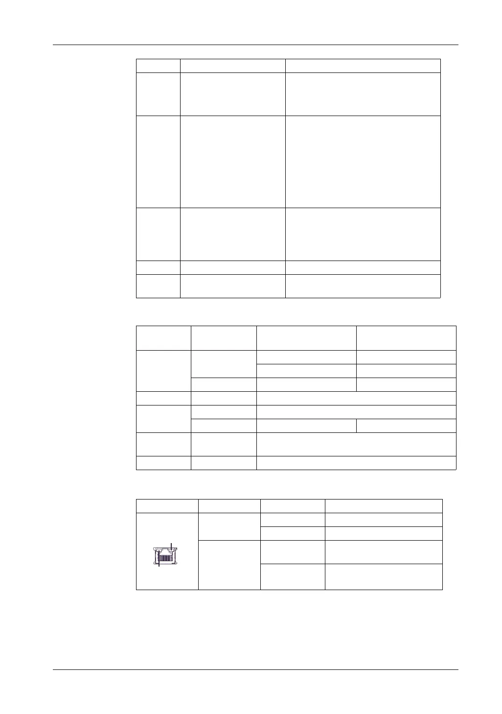
Color Indicator Description
Green (Active) Flashing Data transmission is occurring.
OFF No data transmission.
Green (Link) ON Data transmission is available in
10BASE-T/100BASE-TX.
OFF No connection or subsequent
transmission failure.
Part Name Description
Link
Active
 Loading...