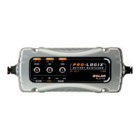
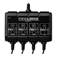
Battery voltage
charge setting
button
Battery type
setting button
Start charging
button
Battery voltage
indicators
Battery type
indicators
Battery start
indicator
Reverse
Polarity
Fault
Power
Charging Charging
Complete
Pro-Logix
TM
Battery Maintainer Settings
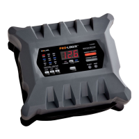
Upon making a proper battery connection (see Section G
or H as applicable), plug AC power cord into an ac
receptacle. All unit LEDs will light momentarily, then only
the LEDs corresponding to power ON and the default
charging settings (12V
, AGM) should stay lit.
The charger is now in Standby Mode.
If the Reverse Polarity Indicator LED lights (and audible
alarm sounds), disconnect from AC power supply
immediately and determine the cause of the alarm.
To charge a battery:
1. Choose a battery voltage charge setting. The default
setting is the 12V mode, which will apply to most
charging applications. To charge in 6V mode, push
the charge setting button until the “6V” LED is lit.
2. Choose a battery type setting. The default setting is
AGM (corresponding to AGM and Gel Cell style
batteries). To charge Standard and Maintenance Free
flooded Acid batteries, push the battery type button
until the “STD” LED is lit.
3. Press the “START” button and the “GO” LED and
“Charging” LED will light. The charger will
automatically commence and complete the charging
process.
Note: If the Battery Fault LED lights, disconnect from
AC power immediately and determine the cause of
the alarm. See Pro-Logix Battery Maintainer Features
for a list of conditions that might cause this warning.
4. When the charging process is complete, the
“CHARGE COMPLETE” LED will light. This indicates
that the initial charging cycle is complete and the
charger is now in Maintenance Mode, and will resume
charging as needed to keep your battery in optimal
condition.
5. When you are finished with the charging process,
disconnect AC power cord from AC outlet, then
disconnect DC leads from vehicle ground (if charging
with battery in vehicle) and battery in the reverse
sequence of the connection procedure.
OPERATING INSTRUCTIONS
I
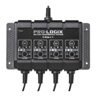
MOUNTING INSTRUCTIONS
J
The charger is designed with 4 mounting
holes. For fixed mounting, select a suitable
location to mount charger. See Section D,
Locating the Charger, for specific location
instructions.