Maintenance Manual V001
FRECCIA
Maintenance Manual V001
FRECCIA
Seite 12 Seite 13
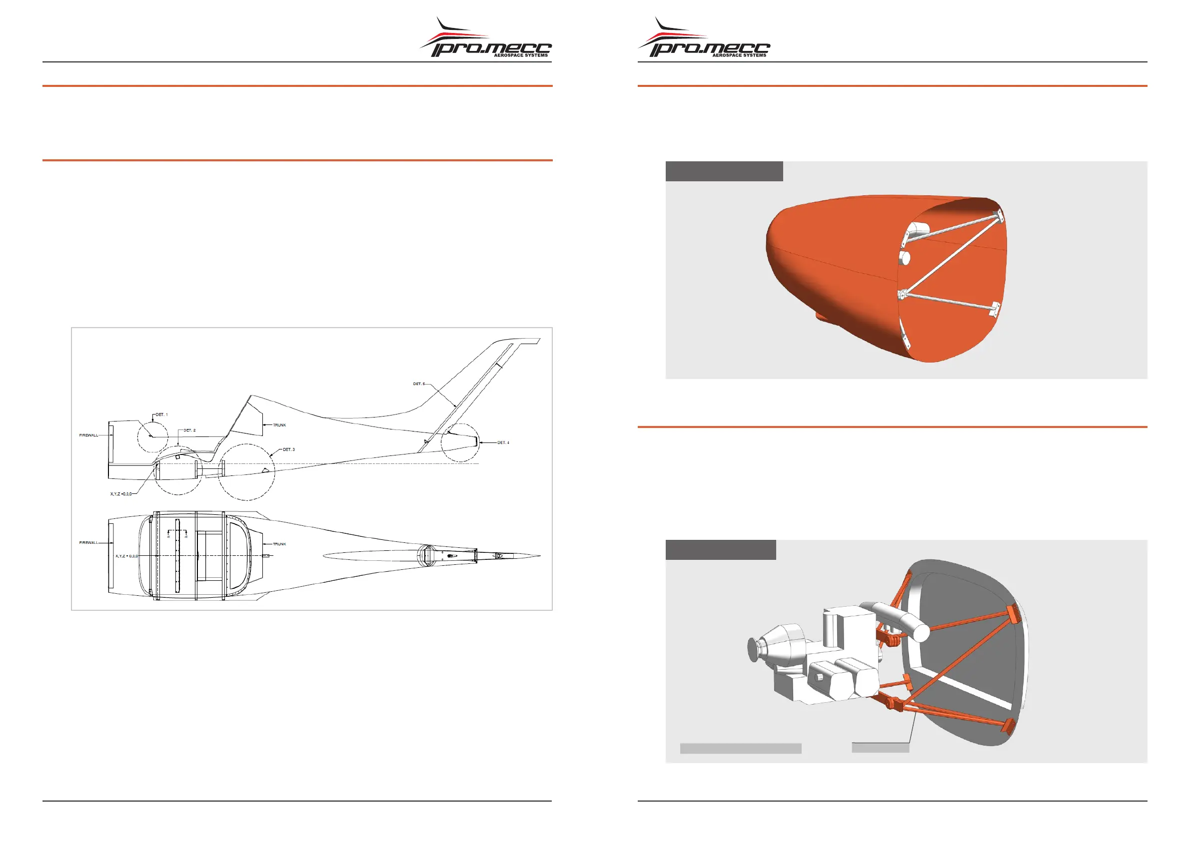
2.2.
ENGINE COVER
The engine is covered by a cover made of a top part and a lower one. The two pieces are fixed to
the fuselage and are fixed each other through collblock.
In the lower part of the cover there are the air intakes to cool the engine.
ENGINE COVER
2.3.
ENGINE MOUNTS
The engine mounts are made of a three-dimensional frame with steel tubes.
The engine mounts have the fittings with the fuselage and the engine through bolts and rubber
silent blocks.
The oil radiator and cooling-fluid radiator are installed on some props.
The order of radiators’ installation in the engine systems is explained in the engine manual.
ENGINE MOUNTS
Engine mountEngine only principle illustraion
2. TECHNICAL DESCRIPTION
This Section contains a description of the airplane and its equipments.
2.1.
FUSELAGE
Fuselage is made up of a shell-like structure in carbon fibre (epoxy resin). Fin is an integral part of
the fuselage.
Wing attaching points are made up of 2 carbon fibre spars going through the shell.
Engine mounting pylon is made up of welded steel tubes. The engine is separated from the fuse-
lage by means of a firewall protection.
Cockpit seats are positioned side by side and their shape is rigid and ergonomic, not adjustable.
Safety belts have three junction points and are adjustable and provided with a single lock easy to
unfasten. The baggage compartment is located behind pilots seats, it is allowed to transport a
maximum of 10-kg. A Plexiglas canopy can be opened lifting.