Method of Operation
Notes:
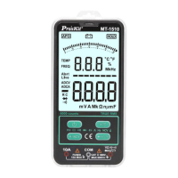
The temperature displayed on startup or other measurement is the current ambient temperature.
Before measuring, vigorously insert the test leads in to make sure the test leads plug is fully inserted
into the sockets.
AC and DC voltage / Resistance / Connectivity - automatic identification and measurements.
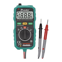
Connect the black test lead and red test lead in to COM input socket and V input socket re-
spectively.
Press the ON/OFF key to turn on the meter.
The probe is parallel to the circuit to be tested, power or resistance. Instrument automatic
identification of AC voltage, DC voltage, resistance.
When measuring resistance, If the measured resistance of less than about 50Ω, the built-in
buzzer calls.
Read from the display of measurement results. Measurement of DC voltage, voltage display
screen at the same time, the red pen test point polarity.
When measuring the AC voltage, both the voltage and frequency are displayed.
Warning
To prevent possible electric shock, fire or personal injury, before measuring the resistance,
please disconnect the power supply of the circuit under test firstly, and fully discharge all the
high voltage capacitors.
Do not try to measure a voltage of more than 600V DC or AC.
After completed all the measurement operation, make sure to disconnect the probe and the
circuit under test.
Diodes, capacitance, and temperature (℃/℉) measurement
Press the “ ℃℉ ”key to switch to diode, capacitance, temperature ℃/℉ measurement
mode
A) Diode measurement
1. Press the “ ℃℉” key to switch to diode test mode.
2. Connect the test leads in black and in red to the positive and negative poles of the diode
to be tested respectively.
3. The meter displays the forward bias value of the diode to be tested. If the polarity of the
test lead is reversed, the meter will display "OL".
B) Capacitance measurement
1. Press the “ ℃℉ ” key to switch to capacitance test mode.
2. Connect the test leads in black and in red to the positive and negative poles of the ca-
pacitance.