Calibration procedure.
Initial calibration is carried out in the factory.
Note – adjustment of these trimmers incorrectly may require service attention by your dealer.
THIS IS NOT COVERED BY THE WARRANTY and your dealer may raise a time and labour
charge for the work.
To use the on-board OFFSET trimmer to perform subsequent calibration
1. Turn the antenna to a known position if the true position differs from the controller display.
2. Adjust the on-board OFFSET trimmer until they are the same.
Note
The Calibration potentiometer will only permit a minor amount of adjustment. If your antenna position
is grossly incorrect, you will need to correct it by repositioning the antenna on the mast.
The complete calibration procedure is the USB - RS232 philosophy.pdf file (for expert only)
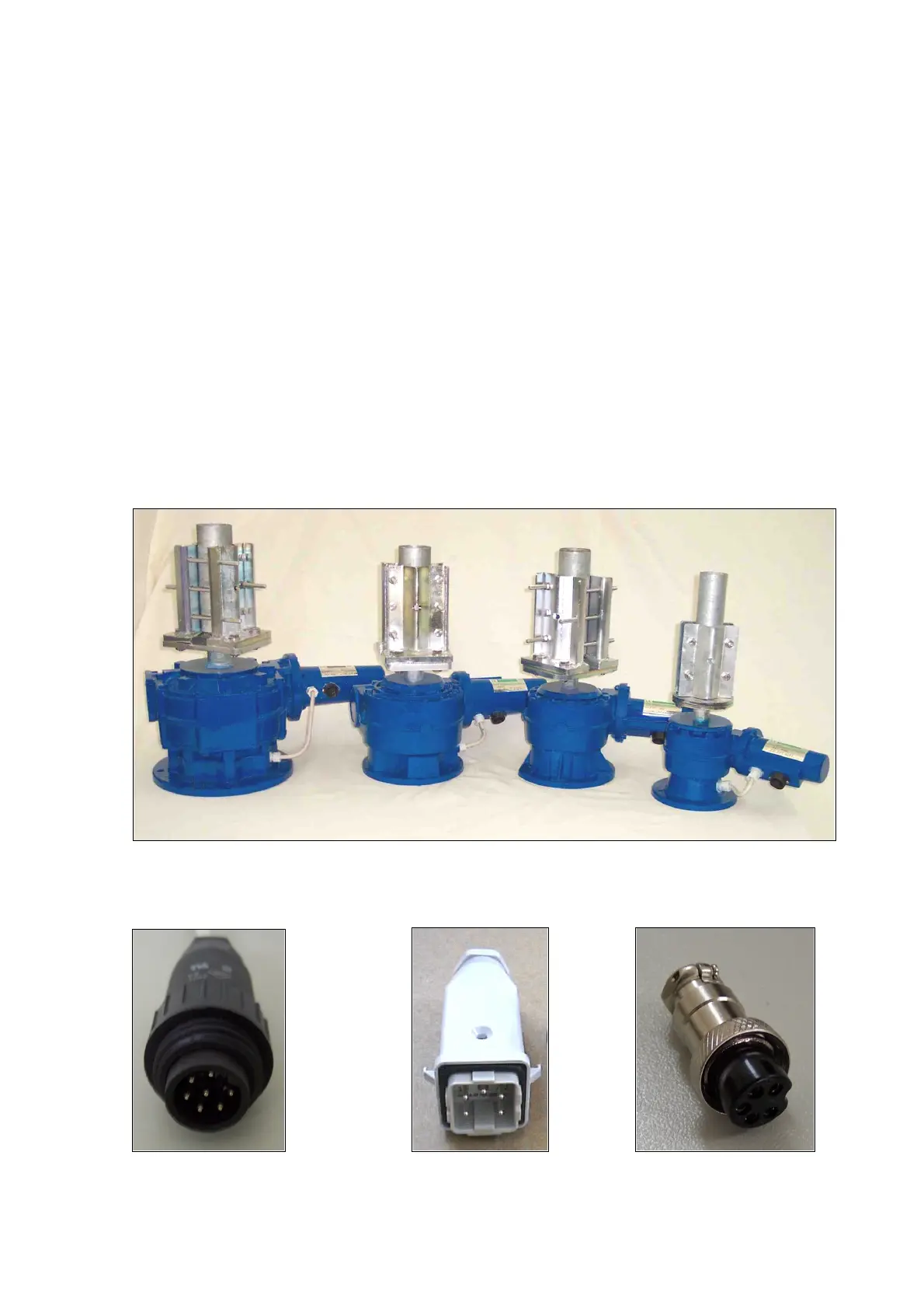
1-4 The rotator
The rotator has a unique design. The motor is located on the side of the machine.
The motor output shaft terminates on a flange, where different kinds of mast clamp, available from us,
may be fixed with bolts. Users may also supply their own clamp.
On the motor side is located a five-contact connector for motor power supply and potentiometer
terminals.
The potentiometer, used as the antenna position reader, is located inside the foot plate, and driven by
the transmission output shaft.
PST 110 - 71 - 61 PST2051 - 641
Rotator cable ends
Rotators end 110-71-61 2051-641 controllers end
8



 To Next Page