5
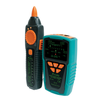
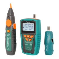
INTRODUCTION
MT-7029 Transmitter:
Do not connect with DC 48V live circuit equipment or it will
result damage.
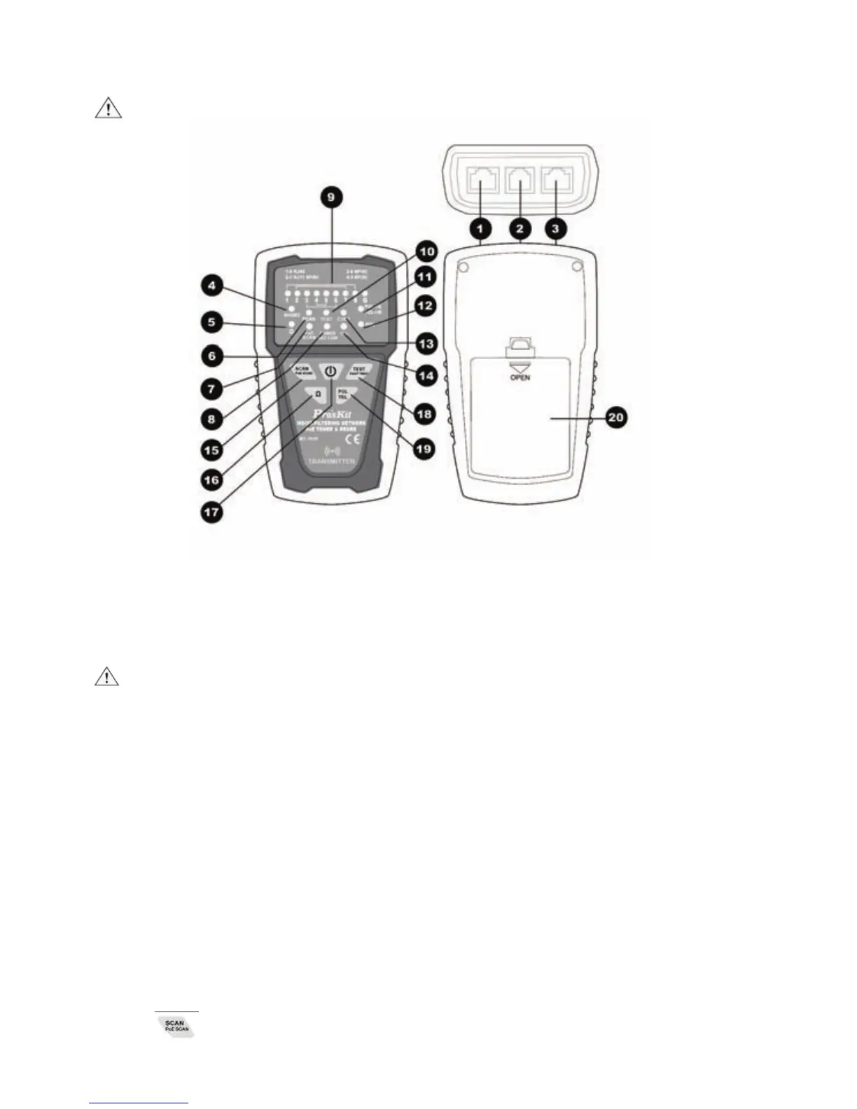
Figure1. MT-7029 Transmitter Diagram
1.「TEST」: RJ45(8 pin)/ RJ11 (6/4/2 pin) cable mapping test socket.
2.「SCAN」: RJ11(6 pin) socket.
3.「SCAN」RJ45 socket.
Caution! Do not plug in any live cable over DC 48V to the
transmitter socket.
4.「SHORT」Continuity test indication
5.「Ω」 Continuity function indicator
6.「SCAN」 Locating and isolating cables function indicator
7.「PoE SCAN」Locating and isolating Cables function indicator
8.「POWER/BAT LOW」 Power ON/OFF & Battery low indicator
9.「1~8、G」 Cable map & Shielded indication
10.「TEST」 Cable map & Shielded function indicator
11.「POL-/G,POL+/R」 Phone line polarity indication
12.「POL」 Phone line polarity function indicator
13.「CONT」Phone line status/polarity indicator
14.「TEL」Phone line status function indicator
15. 「
」Locating and isolating cables function button