6
16.「 」Continuity/short function button
17.「
」Power ON/OFF button
18.「
」Cable map & Shielded function button
19.「
」Phone line polarity function button
20. Battery cover
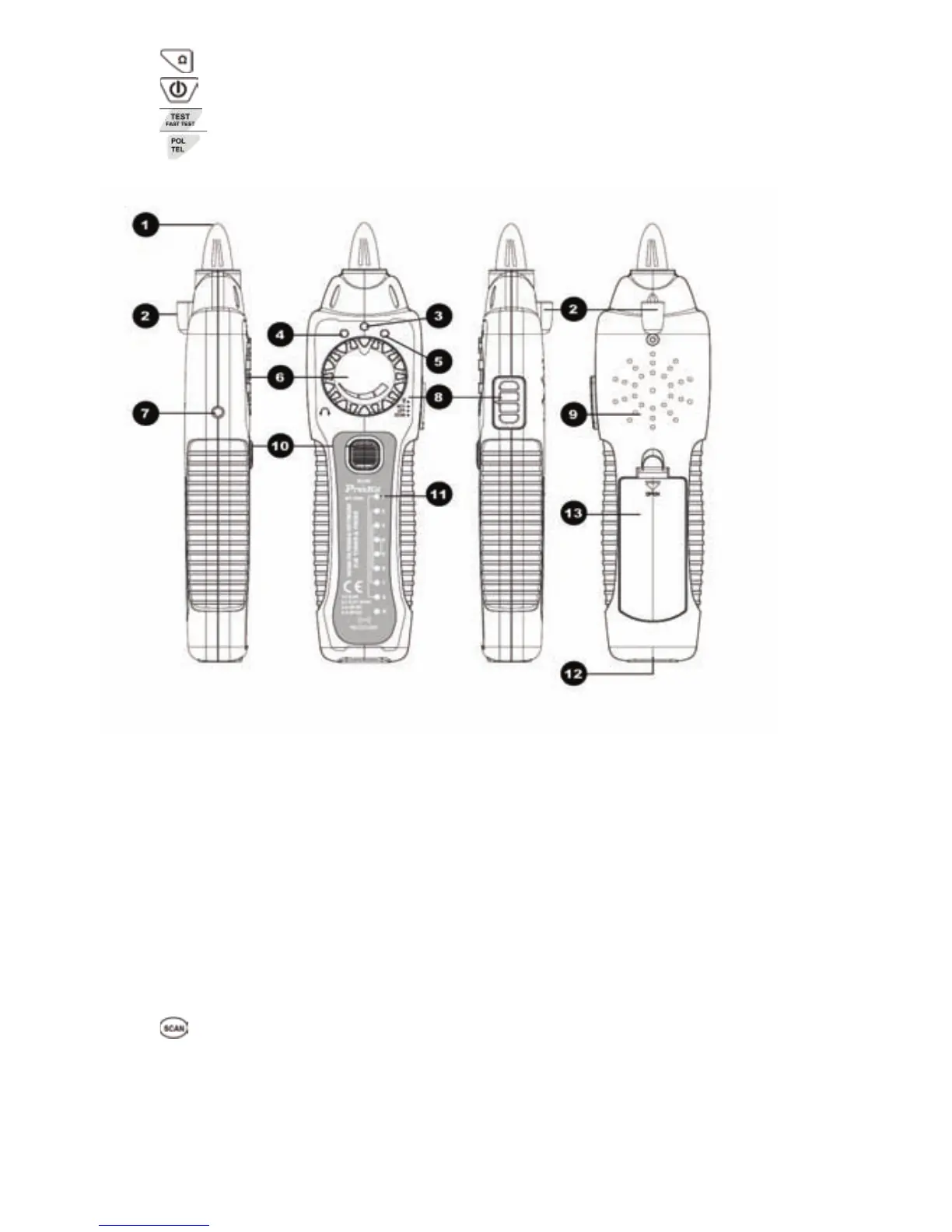
Figure 2. MT-7029 Receiver Diagram
1. Probe:Used for cable tracing and NCV detection.
2. LED light
3. Power ON/OFF indicator
4. NCV indicator
5. Signal status indicator
6. Volume control
7. Earphone jack Φ3.5mm
8. Function switch (LED/NCV/OFF/SCAN mode)
9. Speaker
10.「
」 Locating and isolating cables function button
11.「1~8、G」 Cable map & Shielded indication
12. RJ45(8 pin)/ RJ11 (6/4/2 pin) cable mapping test socket.
13. Battery cover