EasyManua.ls Logo

ProBoat Arleigh Burke Class Destroyer - User Manual

ProBoat Arleigh Burke Class Destroyer
22 pages
Print Icon
To Next Page IconTo Next Page
Loading...
Specifications
Length ........................................................................................ 43 in (1090mm)
Beam ..............................................................................................6 in (156mm)
Motor ...............................................................................................390-size (x2)
Weight ...............................................................................................5 lb(2.3 kg)
Speed Control ........................................................ 50-amp waterproof with reverse
Hull Material .......................................................................... Fiberglass composite
Battery ............................................ 7.2V sub-C w/ Tamiya connector (not included)
Radio ............................................................................... 2-channel (not included)
Servo .................................................................Standard steering servo (installed)
www.ProBoatModels.com
®
Owners Manual
Question and Answer IconNeed help?

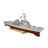
Do you have a question about the ProBoat Arleigh Burke Class Destroyer and is the answer not in the manual?

Summary

Recommended Radio Equipment and Batteries

General Guidelines and Safety Precautions

Operational Guidelines

Advises reading the manual, operating responsibly, and staying clear of hazards.

Safety Precautions

Warns against misuse, emphasizes caution, and states it's a hobby product, not a toy.

Unpacking Your Model

Step 1: Cut Center Foam Support Tape

Use a knife to cut tape securing the two center foam supports to the inner box.

Step 2: Lift Front Foam Support

Carefully lift the front foam support straight up and out of the box.

Step 3: Remove Rear Support Foam

Remove the small piece of foam securing the larger section of the rear support.

Step 4: Lift Rear Foam Support

Carefully lift the rear foam support straight up and out of the box.

Step 5: Trim Wire Ties and Hull

Use side cutters to trim wire ties at the hull rear; lift hull front slightly, then lift hull from box.

Step 6: Cut Main Tower Foam Tape

Use a knife to cut tape securing the packing foam for the main tower to the box.

Step 7: Lift Main Tower Packaging

Carefully lift the main tower and its packaging from the box.

Step 8: Cut Main Tower Securing Ties

Cut three ties securing the main tower to packaging; support tower to prevent damage.

Basic Assembly

Step 2: Connect Receiver Leads

Plug speed control lead into throttle port and rudder servo lead into steering port of receiver, ensuring correct polarity.

Step 3: Mount Receiver and Route Antenna

Attach receiver to servo mounting plate with hook/loop tape; route antenna wires inside hull.

Step 6: Power On Transmitter and Connect Battery

Turn transmitter switch ON and connect the battery to the lead from the speed control.

Step 7: Check Rudder Operation

Verify rudders move right when steering wheel rotates clockwise; adjust servo reversing if needed.

Step 7 (cont.): Check Propeller Operation

Ensure right propeller rotates clockwise and left rotates counterclockwise when trigger is pulled; adjust servo reversing if needed.

Accessory Installation

Warranty Services

Questions, Assistance, and Repairs

Provides contact information for questions, assistance, and repairs via email or phone.

Inspection or Repairs Process

Details the RMA process, packing, shipping, and required documentation for inspection or repairs.

Warranty Inspection and Repairs

Explains requirements for receiving warranty service, including proof of purchase.

Replacement Parts

ProBoat Arleigh Burke Class Destroyer Specifications

General IconGeneral
BrandProBoat
ModelArleigh Burke Class Destroyer
CategoryToy
LanguageEnglish

Related product manuals