20
ENG ITA
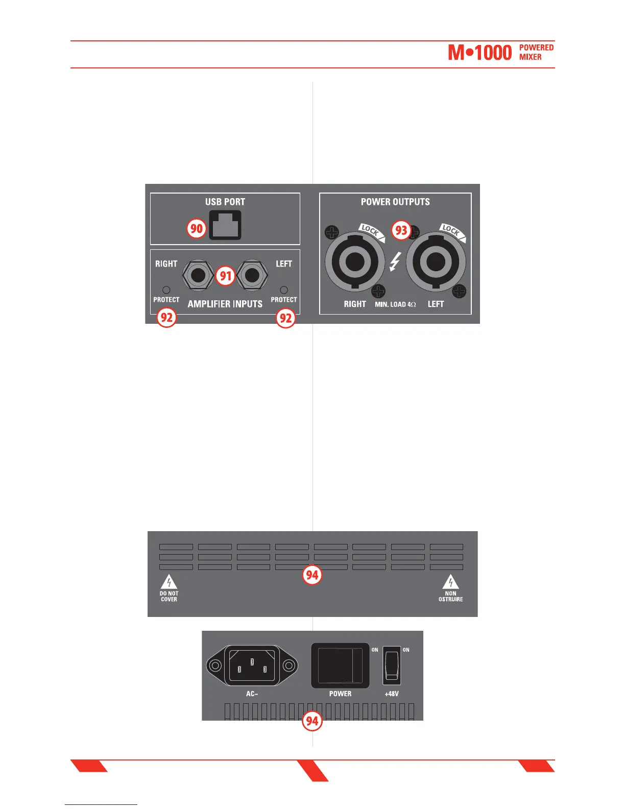
93. POWER OUTPUTS L & R speakon output
These speakon connectors are the outputs of the built-in 500+500W
power ampli ers: connect these outputs to the speakers.
IMPORTANT: be sure that the impedance of the speakers is not less
than 4 ohms, otherwise the ampli er will protect itself. Make certain
to always use only power cables for speakers and not signal cables.
Normally these connectors provide the ampli ed signal of the MAIN
MIX bus (85) or, as
speci ed above, the
ampli ed signal of
any output or
source connected
to the AMPLIFIER
INPUTS L&R (91).
Each amplifier's
channel has a
built-in LIMITER
to avoid excessive
distortion: use the
LED METER (86) to
display the MAIN
MIX (60) signal and
to check when the LIMITER is working.
IMPORTANT: in order to get from the built-in ampli er the maximum
power without excessive signal compression and/or distortion, when
the meter displays the MAIN MIX level, you should avoid the signal to
exceed continously the AMP LIMIT mark (86).
94. AIR VENTS
Air vents for the ampli er’s cooling.
IMPORTANT: IN ORDER FOR THE MIXER TO WORK CORRECTLY, IT’S
VERY IMPORTANT TO KEEP THE AIR VENTS ALWAYS FREE AND ABLE TO
PROVIDE A PROPER AIR CIRCULATION.
93. POWER OUTPUTS L & R speakon output
Questi connettori speakon sono le uscite dell'ampli catore interno da
500+500W: collegare queste uscite agli altoparlanti.
IMPORTANTE: assicurarsi che l'impedenza degli altoparlanti non sia
inferiore a 4 ohm, altrimenti l'ampli catore andrà in protezione.
Assicurarsi sempre di usare esclusivamente cavi di potenza adatti
per collegare gli altoparlanti e non cavi di segnale.
Normalmente
questi connettori
restituiscono il
segnale ampli cato
del bus MAIN MIX
bus (85) o, come
speci cato sopra, il
segnale ampli cato
di qualsiasi
sorgente connessa
agli ingressi jack
AMPLIFIER INPUTS
L&R (91).
Ciascun canale
dell'ampli catore
ha un limitatore interno di segnale (LIMITER) che previene una distorsione
eccessiva: usare gli indicatori di livello LED METER (86) per visualizzare il
segnale MAIN MIX (60) e controllare quando il LIMITER stà lavorando.
IMPORTANTE: per ottenere dall'ampli catore interno il massimo
della potenza evitando una eccessiva compressione o distorsione
del segnale, quando i meter visualizzano il livello del MAIN MIX,
si consiglia di non oltrepassare in modo persistente il livello
contrassegnato dall'indicazione AMP LIMIT.
94. PRESE D'ARIA
Prese d’aria per il ra reddamento dell’ampli catore interno.
IMPORTANTE: PER NON COMPROMETTERE IL CORRETTO
FUNZIONAMENTO DELL’AMPLIFICATORE, E’ MOLTO IMPORTANTE CHE
LA PRESA D’ARIA SIA MANTENUTA SEMPRE LIBERA, PER CONSENTIRE
UNA CORRETTA CIRCOLAZIONE DELL’ARIA DI RAFFREDDAMENTO.
REAR PANEL
PANNELLO POSTERIORE