5
Models LPFA40PF, RMC-FA60PF, RMC-FA125PF, and RMC-FA150PF
ProFitter
TM
Operating Instructions & Parts Manual
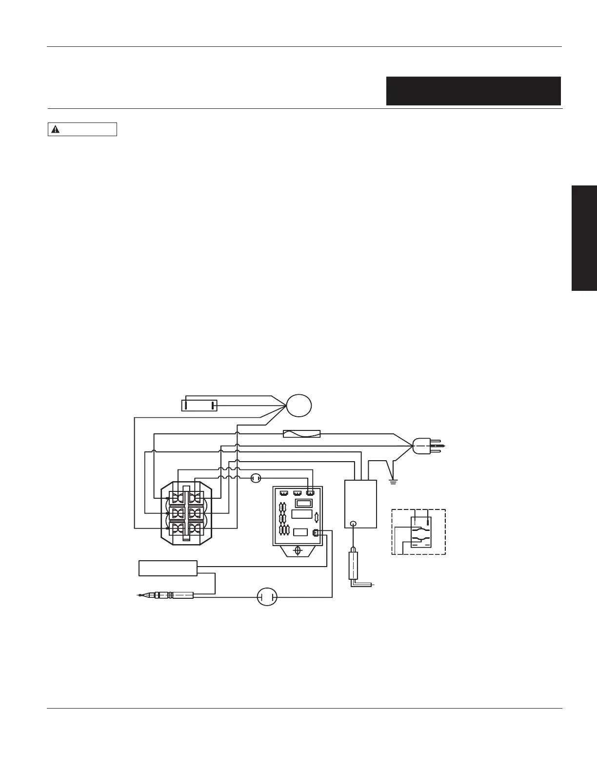
Figure 2 – Continuous Spark Models RMC-FA125PF and RMC-FA150PF
Motor
White
Blue
White
White
White
Fuse
Black
White
Black
Earth
Black
Green
Spark
Module
Black
Black
White
Green
Power Cord
Control Valve
Yellow
Thermocouple
Yellow
Thermal Switch
Ignitor
Alt. Relay
Earth (Out Shell)
Condenser
Multi Receptacle Housing
White
Yellow
Blue
Blue
PCB/
Relay
Black
Back
Pressure
Switch
White
If any original wiring supplied with the
heater must be replaced, it must be with
type AWG 105°C wire or its equivalent,
except as indicated.
E
N
G
L
I
S
H
LPFA40PF, RMC-FA60PF, RMC-FA125PF, RMC-FA150PF
NEVER LEAVE THE HEATER
UNATTENDED WHILE BURNING!
NEVER LEAVE THE HEATER
UNATTENDED WHILE BURNING!
For Technical Support or Troubleshooting, Call: 1-877-447-4768, 8:30 am - 4:30 pm CST www.ghpgroupinc.com
Wiring Diagrams
• Ensure that the ow of combustion and ventilation air exchange cannot become obstructed.
• As the building ‘tightens up’ during the construction phases ventilation may need to be increased.
Air Quality Hazard
(Continued)
USA – Ceiling Limit
(Short Term Exposure Limit = 15
minutes)
CO
CO
2
NO
2
5 ppm
Canada 8-hr time weighted
average WorkSafe BC OHS
Guidelines Part 5.1 and Ontario
Workplaces Reg 833
25 ppm
5000 ppm
3 ppm (Reg 833)
Canada STEL (15 minutes Reg
833/1 hour WSBC) WorkSafe
BC OHS Guidelines Part 5.1 and
Ontario Workplaces Reg 833
100 ppm
15000 ppm (WSBC)
30000 ppm (Reg 833)
1.0 ppm (WorkSafeBC)
5.0 ppm (Reg 833)