PD5100 TROUBLESHOOTING GUIDE
Page 2
The Automatic Transfer Switch (ATS) is designed to be quickly tested for proper operation and repair if necessary. All critical
circuits are located on the easily replaceable circuit board. The following will describe how to test for proper circuit board op-
eration and how to replace it if necessary.
1. Disconnect all AC power from the RV and make sure the generator is “OFF”
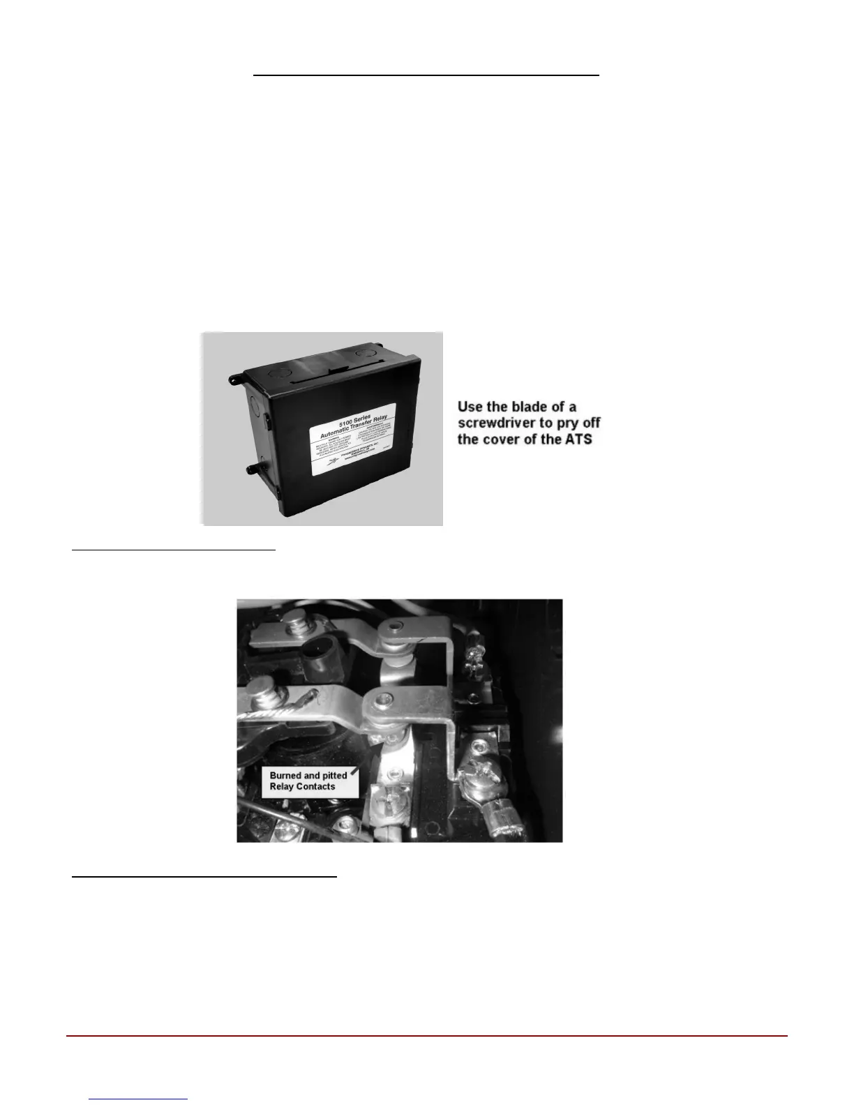
2. Remove the cover from the ATS by sliding a screwdriver blade under the edge of the cover and pry off.
3. Start the generator and wait 20-45 seconds to see if the relay will energize. If the relay does not energize, go to Step #
4. If the relay energizes, but the Generator still does not provide 120 VAC power to the RV, use an AC Voltmeter to
check for 120 VAC power from the Generator to the ATS. Then check for 120 VAC at the N.O. (Normally Open)
terminals of the relay. If 120 VAC power is present at the N.O. terminals of the relay, you have a wiring problem be-
tween the ATS and the RV AC Distribution panel. If no voltage is measured on the N.O. terminals, the entire unti
will need to be replaced.
4. With the Generator running use an insulated screwdriver to carefully plush down on the center arm of the relay, until
the center arm of the relay makes contact with the N.O. contacts of the relay. If AC power is now present in the RV
the circuit board in the ATS has failed and must be replaced.
Relay Contacts Burned and Pitted
If the Relay Contacts are burned and pitted (see photo below), the Generator has a problem and it’s voltage is dropping below
90 VAC under load. If this problem occurs, you must repair or replace the Generator and the complete ATS.
REPLACING THE ATS CIRCUIT BOARD
WARNING: Disconnect all AC power from the RV and turn the generator “OFF”.
1. Before replacing circuit board: With the power off check for 3-7k ohms on the red and yellow wires to the relay. If the
coil checks open or shorted, replace the entire unit.
2. Pull the circuit board out of the plastic housing and then using a screwdriver blade, pry the Yellow, White, Black and
Red wires off the connectors on the circuit board.
Consult a licensed electrician or an RV technician for installation assistance
 Loading...