WIRING DIAGRAMS:
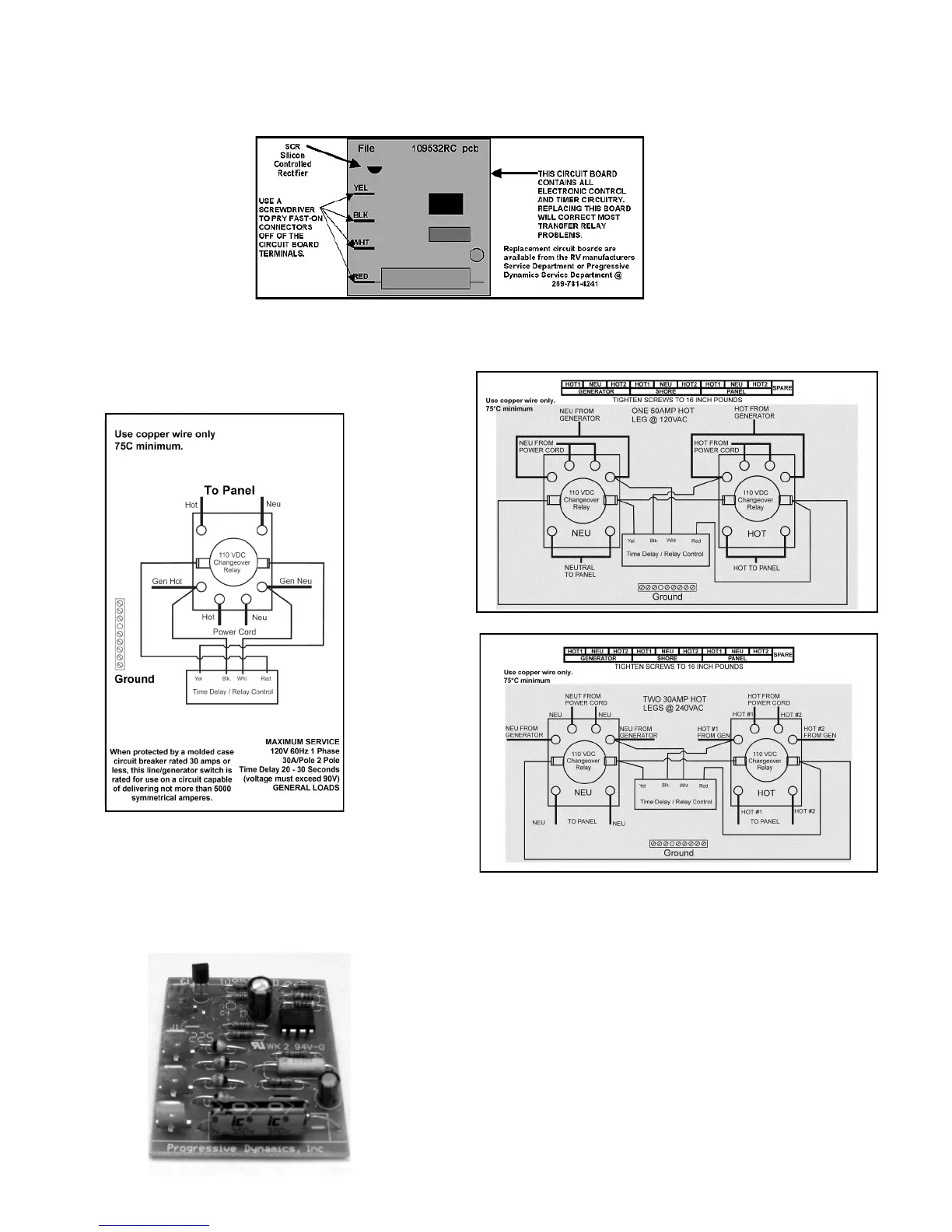
2. Pull the circuit board out of the plastic housing and then using a screwdriver blade, pry the Yellow, White, Black and
Red wires off the connectors on the circuit board.
3. Replace the Circuit Board and reconnect the four (4) wires and test the system by starting the Generator. The Relay
should energize in 20-45 seconds. If the relay does not energize, the relay coil is probably open and the ATS must be
replaced.
Page 3
30A@120V
30A@24 0V
50A@120V
PD51 Time-Out Disable
The PD51 control board is not field modifiable. To disable the time-out
function, install a jumper wire in the area marked J1 on the PCB. This
modification will require removing the circuit board and soldering a
jumper wire in the J1 location.