PROHEAT M-SERIES SERVICE MANUAL
3-15
Fuel Supply Pump – Check:
a) Fuel Supply Pump pressure and operation.
Test Procedure – Fuel Supply Pump pressure:
a) Disconnect all harnesses at the PCM.
b) Disconnect the fuel supply line.
c) Loosen and back out the burner head mounting (2) bolts five to six turns
allowing enough room to rotate the burner head 15° counter-clockwise
and remove.
d) Remove ignition electrode assembly. Use a flat head screwdriver to pry
the electrode assembly out.
e) Remove the flame shield. Rotate to match the mounting square.
f) Disconnect the Fuel Shut-off Valve and Ignition Module connectors at the
PCM. Ensures that fuel will not spray and/or light during testing.
g) Remove the Fuel Supply Pump test port plug and install test gauge.
h) Reconnect the power and switch harnesses at the PCM.
i) Reconnect the fuel supply line.
j) Switch the PROHEAT on and read the fuel pressure (should be 3 – 12 PSI):
If the pressure is out of range, Go to Fuel Supply Pump cleaning, page 3-16.
If the pressure reads OK, review Fuel System troubleshooting, page 3-3.
START: Fuel System Step 7
(1 Flash)
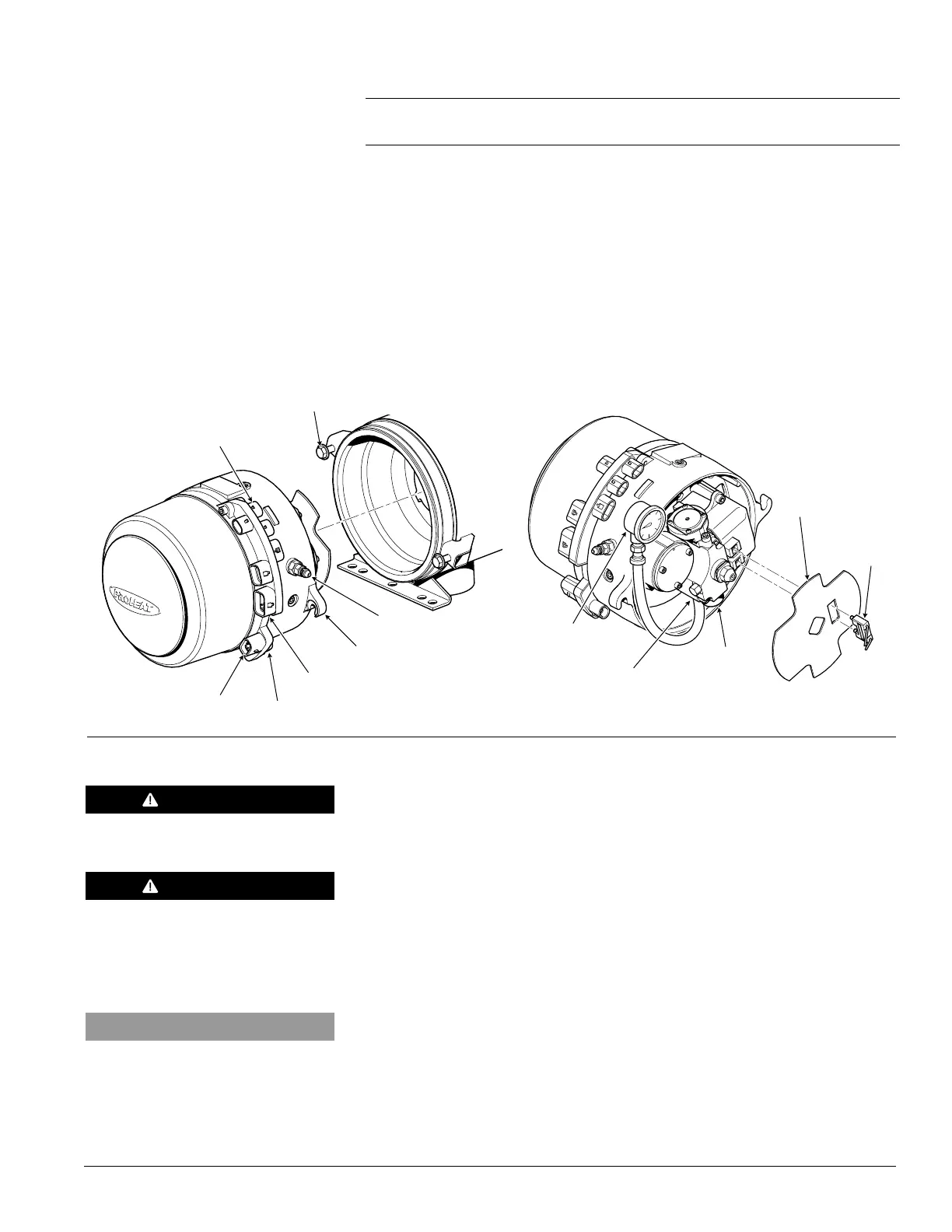
Figure 3-16: Burner Head Removal and Fuel Pressure Test
GAUGE (P/N PK0067)
FUEL SUPPLY PUMP TEST PORT
FUEL
SHUT-OFF
SOLENOID
FLAME SHIELD
IGNITION
ELECTRODE
ASSEMBLY
WARNING
Flammable.
WARNING
To avoid the risk of shock and to
ensure that the PROHEAT does not
fire, disconnect the Ignition Module
connector at the PCM.
NOTICE
Leaving the Temperature Sensor(s)
disconnected ensures that the burner
head will enter purge mode and run
for a maximum of three minutes.
MOUNTING EARS (2)
MOUNTING BOLTS (2)
TORQUE = 100 in-lbs
COOLANT PUMP
SWITCH INPUT
TEMP SENSOR 1
POWER
FUEL INLET
 Loading...