PROHEAT M-SERIES SERVICE MANUAL
3-16
Fuel Supply Pump cleaning:
a) Disconnect all harnesses at the PCM.
b) Disconnect the fuel supply line.
c) Loosen and back out the burner head mounting (2) bolts five to six turns
allowing enough room to rotate the burner head 15° counter-clockwise
and remove.
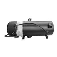
d) Locate the pressure relief valve cap and remove with a slot screwdriver.
Careful not to lose any of the internal components that may fall out.
e) Remove the spring from the cavity.
f) Remove the ball bearing from the cavity.
g) Inspect and clean all components.
h) Inspect and clean the cavity. Pay close attention to the center hole in the
cavity for any debris or a damaged edge. The edge of the hole should be
smooth with no nicks, do not use any tool that may damage this edge as
this will cause loss of fuel pressure.
i) Place ball bearing back in cavity on the center hole.
j) Place spring back in hole with brass ball guide on top of ball bearing.
k) Install pressure relief valve cap.
l) Re-test the Fuel Supply Pump. Start from item 'e' in Test procedure –
Fuel Supply Pump pressure, page 3-15.
If the Fuel Supply Pump pressure tests OK, go to item 'm'.
If the Fuel Supply Pump pressure is still incorrect, go to Fuel Supply
Pump replacement
m) Reassemble the burner head.
n) Reinstall electrical harnesses and fuel supply line.
o) Switch the PROHEAT on and operate for at least one complete cycle.
Observe the operation.
Fuel Supply Pump replacement:
a) Disconnect and remove the Ignition Module. Go to page 3-19.
b) Remove Fuel Nozzle. Go to page 3-6.
c) Remove Fuel Regulator. Go to page 3-11.
d) Disconnect and remove Fuel Shut-off Valve. Go to page 3-8.
e) Remove blower housing (2) screws and blower housing.
f)
Remove blower retaining snap ring and slide the blower off the Motor shaft.
g) Disconnect the Motor connector at the PCM. Remove the PCM.
h) Remove Motor (4) mounting screws using a 4 mm Allen wrench.
i) Remove the Motor.
j) Remove the Air Compressor gear retaining snap ring and gear.
k) Remove Air Compressor (2) screws, Air Compressor, (2) O-rings from the
Fuel Supply Pump.
l) Reinstall all components in reverse order to new Fuel Supply Pump.
m) Reinstall the burner head by mounting it against the heat exchanger face,
turning clockwise to engage the mounting ears on the bolts.
n) Reinstall electrical harnesses and fuel supply line.
o) Switch the PROHEAT on and operate for at least one complete cycle.
Observe the operation.
Figure 3-17: Pressure Relief Valve Cap
PRESSURE RELIEF VALVE CAP
TORQUE = 25 in-lbs
SPRING
BALL BEARING
BALL GUIDE
 Loading...