PROHEAT M-SERIES SERVICE MANUAL
3-19
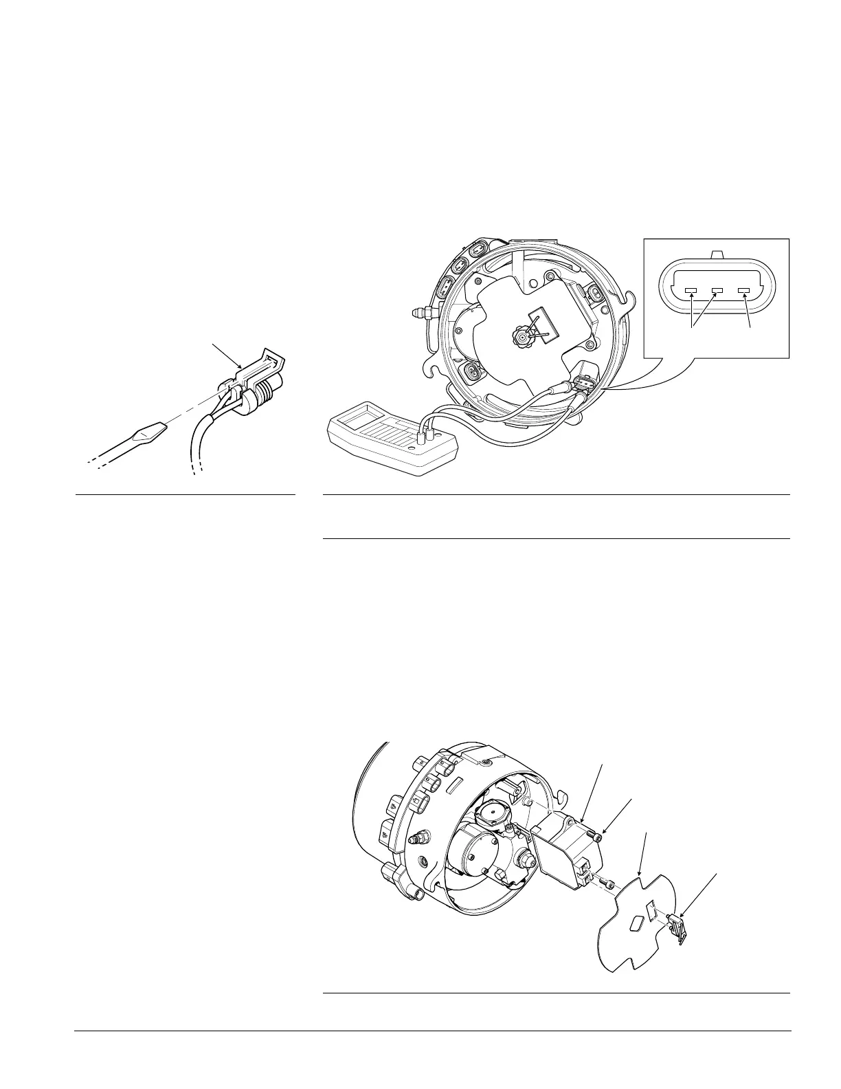
c) Switch the PROHEAT on and measure across pins A and C of the PCM
Ignition Module connection.
If the correct system voltage (12 or 24) is measured, then measure
across pins B and C (should read 0 Volts).
If both of the measurements are correct, then replace Ignition Module.
Go to Ignition Module replacement.
If either of these measurements are incorrect, the PCM is faulty. Go to
PCM replacement, page 3-39.
Ignition Module replacement:
a) Remove ignition electrode assembly. Use a flat head screwdriver to pry
the electrode assembly out.
b) Remove the flame shield. Rotate to match the mounting square.
c) Remove Ignition Module (2) mounting screws and Module.
d) Reinstall the new Ignition Module.
e) Reinstall flame shield and electrode assembly.
f) Reconnect Ignition Module connector at the PCM.
Figure 3-21: PCM Ignition Module Connection Measurement
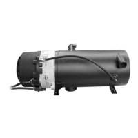
LOCK
Figure 3-20: Connector Removal
A
BC
Figure 3-22: Ignition Module Replacement
IGNITION MODULE
SCREWS (2)
TORQUE = 75 in-lbs
FLAME SHIELD
IGNITION ELECTRODE
ASSEMBLY
RED (+) BLACK (-)
 Loading...