PROHEAT M-SERIES SERVICE MANUAL
3-20
Flame Sensor – Check:
a) Flame Sensor operation.
b) Combustion tube orientation.
Test Procedure – Flame Sensor circuit:
a) Disconnect all harnesses at the PCM.
b) Disconnect the fuel supply line.
c) Loosen and back off the burner head mounting (2) bolts five to six turns
allowing enough room to rotate the burner head 15° counter-clockwise
and remove.
d) Disconnect the Ignition Module connector at the PCM.
e) Check for contamination on the Flame Sensor. Clean if necessary using
electrical contact cleaner or warm soapy water.
f) Reconnect the power harness and the remote test switch with the switch
in the off position.
START: PCM Flame
Sensor Circuit
(1 Flash)
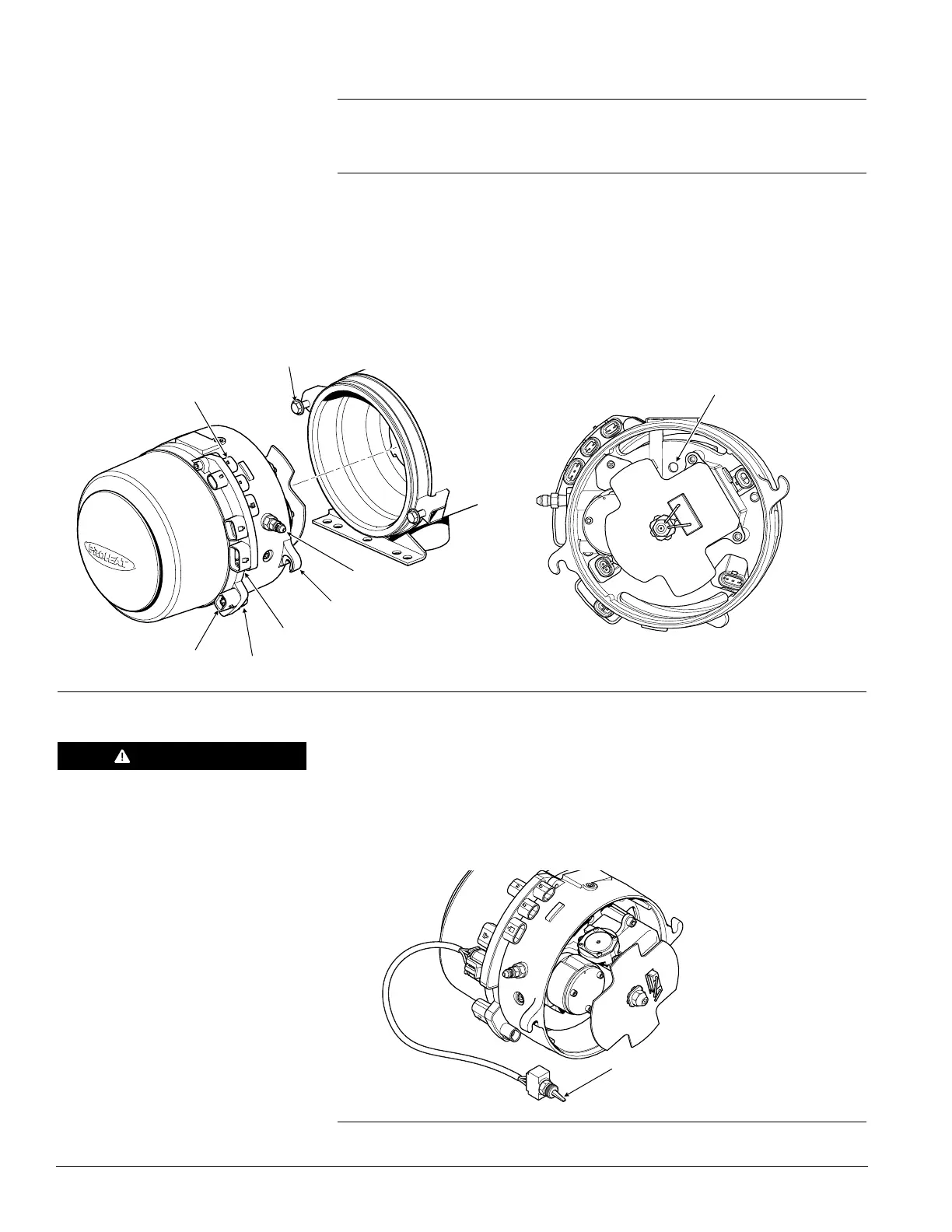
Figure 3-23: Burner Head Removal and Flame Sensor Location
REMOTE TEST SWITCH IN
OFF POSITION (P/N PK0091)
FLAME SENSOR PORT
WARNING
To avoid the risk of shock and to
ensure that the PROHEAT does not
fire, disconnect the Ignition Module
connector at the PCM.
Figure 3-24: Remote Test Switch Connection
MOUNTING EARS (2)
MOUNTING BOLTS (2)
TORQUE = 100 in-lbs
COOLANT PUMP
SWITCH INPUT
TEMP SENSOR 1
POWER
FUEL INLET
 Loading...