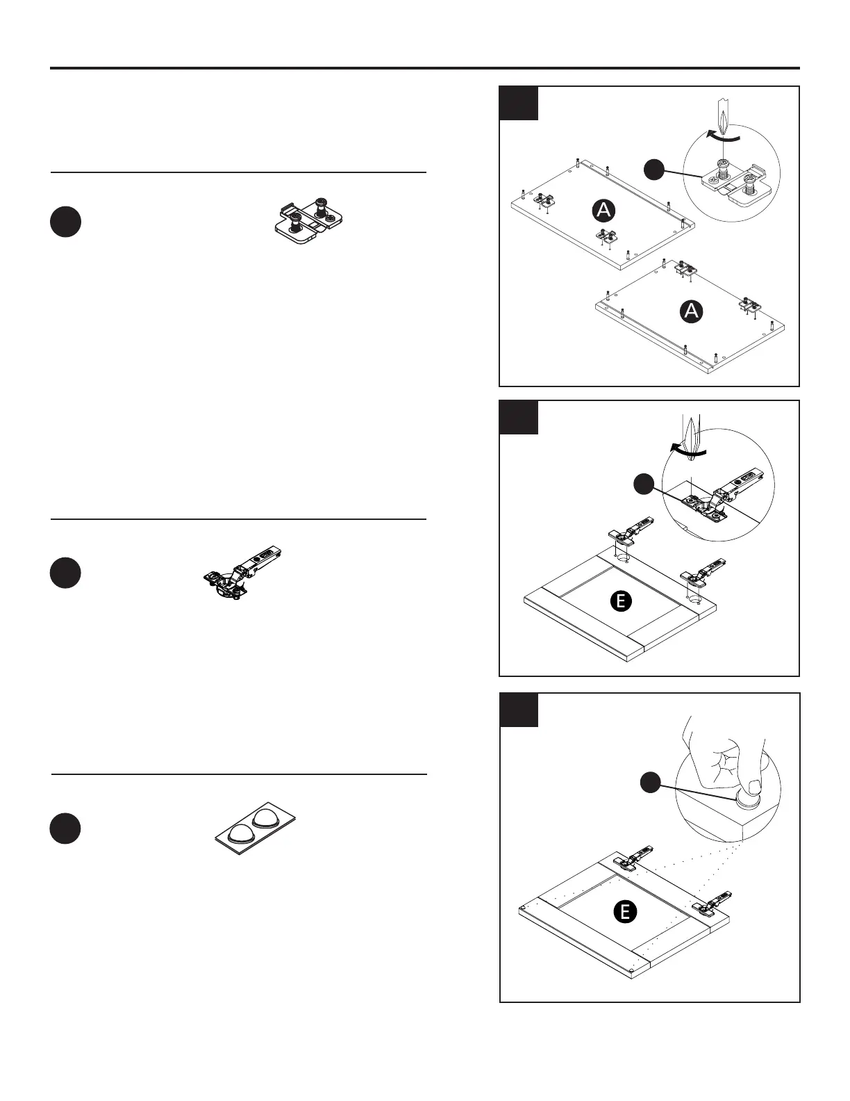
7
ASSEMBLY INSTRUCTIONS
5
4
6. Place the bumper on the door as shown
6
Hardware Used
Hardware Used
Hardware Used
Hinge mounting plate
105
o
Hinge
Bumper 2MM
x 4
x 4
x 4
DD
EE
FF
DD
EE
FF
4. Using a phillips head screwdriver, attach the
mounting plate as shown in the illustration.
6. Insert the hinge in the bore hole. Using a Phillips
head screwdriver, turn the pre-installed screws
clockwise to lock into place.