Beta Draft Confidential
10 Proliphix Internet Managed Thermostat (IMT) Installation Guide
Part No. 600-03100-000, Rev. 4
Installing and Wiring the Thermostat
Connecting CAT5/CAT5E/CAT6 Wiring for Ethernet Networks to
IMT550c Thermostats
The label located on the inside of the base plate (see Figure 6) shows several
color-coded wiring schemes for Ethernet CAT5/CAT5E/CAT6 connections.
To wire the Ethernet network, refer to Figure 6 and match the label number to the
Proliphix base plate number for CAT5/CAT5E/CAT6 color coding.
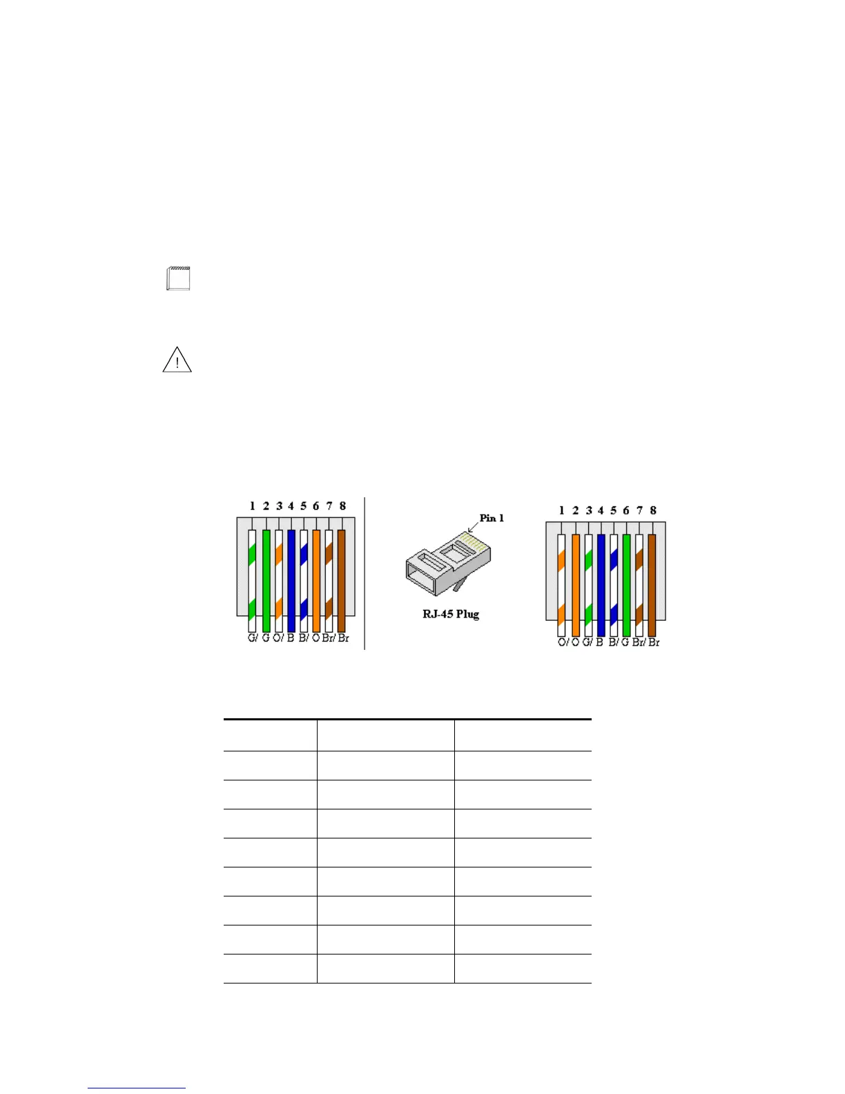
Figure 6 shows the RJ-45 Ethernet plug pinout assignments for the T568A and T568B
wiring standards.
Figure 6 RJ-45 Ethernet Plug Pinout Assignments for T568A and T568B
Table 4 describes the pinout assignments for the T568A and T568B wiring standards.
If the other end of the CAT5/CAT5E/CAT6 cable is connected to a Proliphix
EPA-20/60 Ethernet Power Adapter, follow the wiring scheme for T568A.
All wiring must conform to local codes and ordinances. The distance between
CAT5/CAT5E/CAT6 cables and HVAC cables should be a minimum of one inch.
Table 4 T568A and T568B Pinout Assignments
Pin Number T568A Wire Color T568B Wire Color
1 Green/White Orange/White
2 Green Orange
3 Orange/White Green/White
4Blue Blue
5 Blue/White Blue/White
6 Orange Green
7 Brown/White Brown/White
8 Brown Brown