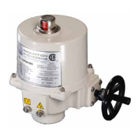
Torque Switch cams shown with the lower
cam in a TRIPPED position (high torque in the
CCW Output Drive Direction)
High Torque Cam
(bottom) for CCW
Output Drive Rotation
High Torque Cam
(top) for CW Output
Drive Rotation
High Torque Switch
(bottom) for CCW
Output Drive Rotation
High Torque Switch
(top) for CW Output
Drive Rotation
WARNING! Do NOT
adjust the torque
switch cam settings.
This will VOID the
warranty.
T
est Torque Switch CCW Mechanical Operation
1. Rotate the manual override handwheel in a CCW direction to continue to drive the output drive in a CCW direction until
the drive system reaches the end of its MECHANICAL travel either by coming into contact with the mechanical stop
screw OR it reaches the end of the valve (or damper) travel. This is indicative of an increasing force required to rotate
the handwheel.
2. At this point the torque switch cam shaft starts to rotate in a CW direction. (There is no need to continue to rotate the
handwheel further in the CCW direction, the torque switch cam shaft would continue to rotate in the CW direction until
the LOWER cam trips the LOWER high torque switch).
3. At this point, stop rotating the handwheel as you’ve simulated reaching the electrical drive limit of the actuator under
excessively high torque situations in the CCW output drive direction.
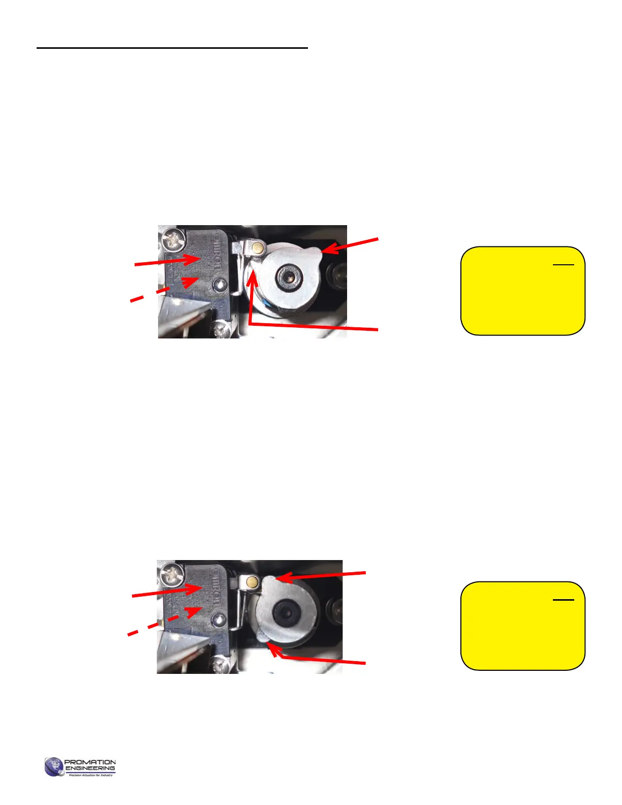
Torque Switch cams shown with the upper
cam in a TRIPPED position (high torque in
the CW Output Drive Direction)
High Torque Cam
(bottom) for CCW
Output Drive Rotation
High Torque Cam
(top) for CW Output
Drive Rotation
High Torque Switch
(bottom) for CCW
Output Drive Rotation
High Torque Switch
(top) for CW Output
Drive Rotation
WARNING! Do NOT
adjust the torque
switch cam settings.
This will VOID the
warranty.
Test Torque Switch CW Mechanical Operation
1. Rotate the manual override handwheel in a CW direction to continue to drive the output drive in a CW direction until
the drive system reaches the end of its MECHANICAL travel either by coming into contact with the mechanical stop
screw OR it reaches the end of the valve (or damper) travel. This is indicative of an increasing force required to rotate
the handwheel.
2. At this point the torque switch cam shaft starts to rotate in a CCW direction. (There is no need to continue to rotate the
handwheel further in the CW direction, the torque switch cam shaft would continue to rotate in the CCW direction until
the UPPER cam trips the UPPER high torque switch).
3. At this point, stop rotating the handwheel as you’ve simulated reaching the electrical drive limit of the actuator under
excessively high torque situations in the CW output drive direction.
4. Generateamid-positionsignalattheelddevicetomovetheactuatoroitsfullCWtripposition.
Commissioning for TS units (continued)
5. Actuator is now commissioned and operational.
Page 15 of 17 P2/3 12 24 VDC Proportional Series
FM_P28 24 PN4-DC Ver E 080223
 Loading...