Commissioning
WARNING! Do NOT
adjust the torque
switch cam settings.
This will VOID the
warranty.
After completing all mounting and wiring procedures and main power is available, it is now possible to commission
the actuator.
1. Utilize the handwheel to rotate the actuator and damper, valve or other connected device through its full travel from
full CW to full CCW and back again to check for any possible interference. Do NOT utilize any mechanical advantage
devices to rotate the handwheel (pipes, wrenches, extension bars, etc.).
2. Manually position the actuator to its mid-stroke position.
3. Make certain the 3 wire orange plug is fully seated on the 3-pin receptacle on the switch board.
4. Apply correct power to the unit.
5. Measure correct power on terminals 1 and 2 on the switch board.
6. Measure correct power on the two heater terminals on the switch board.
7. CommandtheelddevicetogenerateaCCWsignal.TheactuatorrotatesinaCCWdirection(asviewedfromabove).
8. Actuator will stop when it reaches it’s full CCW position.
9. CommandtheelddevicetogenerateaCWsignal.TheactuatorrotatesinaCWdirection(asviewedfromabove).
10. Actuator will stop when it reaches it’s full CW position.
11. Generateamid-positionsignalattheelddevicetomovetheactuatoroitsfullCWtripposition.
12. Actuators with no -TS options are now commissioned and operational. See below for additional -TS steps.
Test Torque Switch functions
1. Generate a 4mA or 20mA control signal and let the actuator
drive towards that CW or CCW position.
2. As the motor is running, simulate a torque switch event: Depress
the top or bottom torque switch and hold it (one will immediately
stop the motor).
3. Release the torque switch.
4. Test recovery from the torque switch event.
• Move the handwheel 2° in either direction
• Signal the motor to drive.
5. Repeat steps 1 through 4 in the opposite direction (20mA or
4mA) to test the opposing direction torque switch functionality.
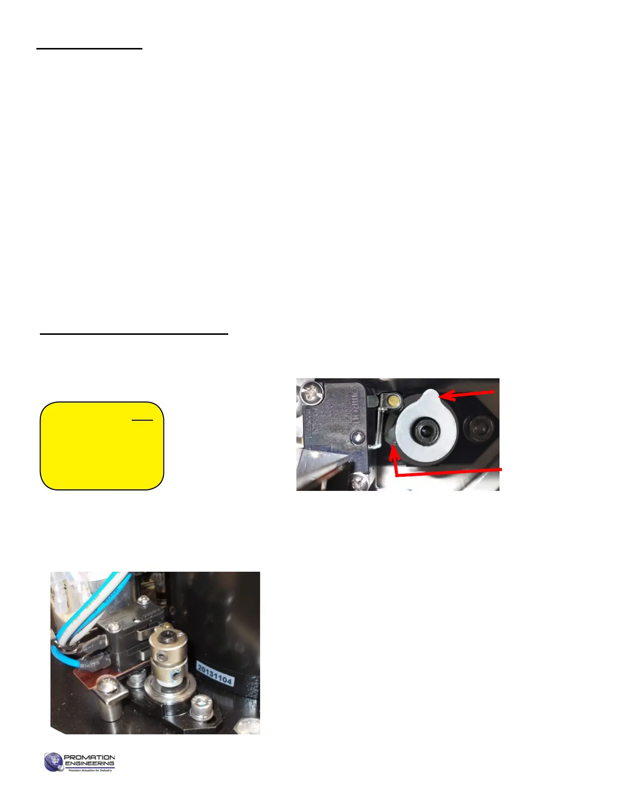
Testing Torque Switch Electrical Operation
TS units incorporate a torque overload protection system. In NORMAL operating
mode, the torque switch drive cam is in this position:
High Torque Cam
(bottom) for CCW
Output Drive Rotation
High Torque Cam
(top) for CW Output
Drive Rotation
High Torque Switch
(top) for CW Output
Drive Rotation
High Torque Switch
(bottom) for CCW
Output Drive Rotation
Commissioning for TS units
Page 14 of 17 P2/3 12V 24DC Proportional Series
FM_P28 24 PN4-DC Ver E 080223
 Loading...