RED YEL GRN FAULT 12, 24
VDC
24,120,
230 VAC
flash OFF OFF
Low Voltage X
Supply voltage is less than 10VDC
flash flash OFF
Motor 1 Stall X X
No motor movement in direction 1 upon
command with motor amperage load
flash OFF flash
Motor 2 Stall X X
No motor movement in direction 2 upon
command with motor amperage load
flash flash flash
Double Stall X
No motor in either direction movement upon
command
flash ON OFF
Motor 1 Current Trip X
Current on motor line 1 is higher than current
trip setting
flash OFF ON
Motor 2 Current Trip X
Current on motor line 2 is higher than current
trip setting
flash ON ON
Double Current Trip X
Current too high in both motor directions
ON OFF OFF
Over Voltage X
Supply voltage is higher than 30VDC
ON flash OFF
Motor 1 No Motion X
No motor movement in direction 1 upon
command with no motor amperage load
ON OFF flash
Motor 2 No Motion X
No motor movement in direction 2 upon
command with low motor amperage load
ON flash flash
Double No Motion X
No motor movement in either direction upon
command with low motor amperage load
OFF OFF flash
Feedback Alarm X X
Feedback signal from potentiometer out of
range or not present
OFF flash OFF
Loss of Command X X
Command signal is disconnected
OFF ON OFF
Command Out of Range X X
Command singal is out of range
OFF flash flash
Feedback Alarm and Loss
of Command
X X
Both potentiometer and command signals are
lost
OFF ON flash
Feedback Alarm and
Command Out of Range
X X
Potentiometric signal is lost, command signal is
out of range
FAULT INDICATORS
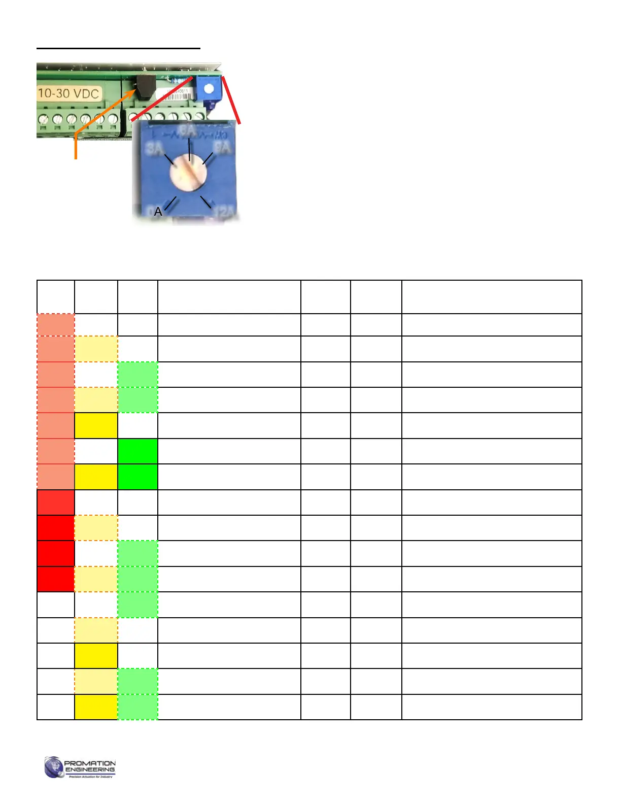
Motor Amperage Limiter
0A
3A
6A
9A
12A
The DC controllers are equipped with adjustable amperage limiting that
is set by the rotational potentiometer adjacent to the J7 connector. The
amperage draw on the motor is limited by the aperage setting as shown
in the inset. TThe setting should be adjusted to a reasonalb elevel above
the running current expected for the actuator and its load. When the motor
currentexceedsthetripsetting,themotoristurnedoandaCurrentTrip
fault condition is indicated.
The amperage limiter setting essentially performs the same function as
torque switches. The limiter is for the actuator motor, so other components
in the system (gears, couplings, packing, seats, etc.) also place a load on
themotor.Theeectofthesecomponentswillvarywithtemperatureand
age. Therefore the amperage draw on the motor may vary accordingly.
The J7 Connector is used in conjuction with local control stations (LCS) or
motor control stations (MCC) for local control of the actuator. Both AC and
DC controllers contain the J7 connector
J7
Connector
Page 13 of 17 P2/3 12 24 VDC Proportional Series
FM_P28 24 PN4-DC Ver E 080223
 Loading...