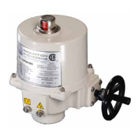
Loosen Mechanical Stops
1. BEFORE power is applied, use a 17mm wrench and a 5mm hex key to
loosen the LEFT and RIGHT SIDE mechanical stops.
2. Turn the stop screws 5-6 turns CCW to allow electrical cam stop adjustment
to keep the internal stops from running into the mechanical stop screws.
3. Leave the stop screws out until controller calibration is complete.
Understanding Cam Operation
4. The lowest cam, Cam 1 controls SW1, a CW limit switch secondary to the
controller board. It will interrupt power to the board and motor if it changes
state and shows as a fault on the controller board.
5. The second cam, Cam 2 controls SW2, a CCW limit switch secondary
to the controller board. It will interrupt power to the board and motor if it
changes state and shows as a fault on the controller board.
6. The third cam, Cam 3 controls SW3, a CW (CLOSED) auxilary switch
connected to the optional outputs 7-9 of the 430-10100 Switch Card.
7. The uppermost cam, Cam 4 controls SW4, a CCW (OPEN) auxilary switch
connected to the optional outputs 10-12 of the 430-10100 Switch Card.
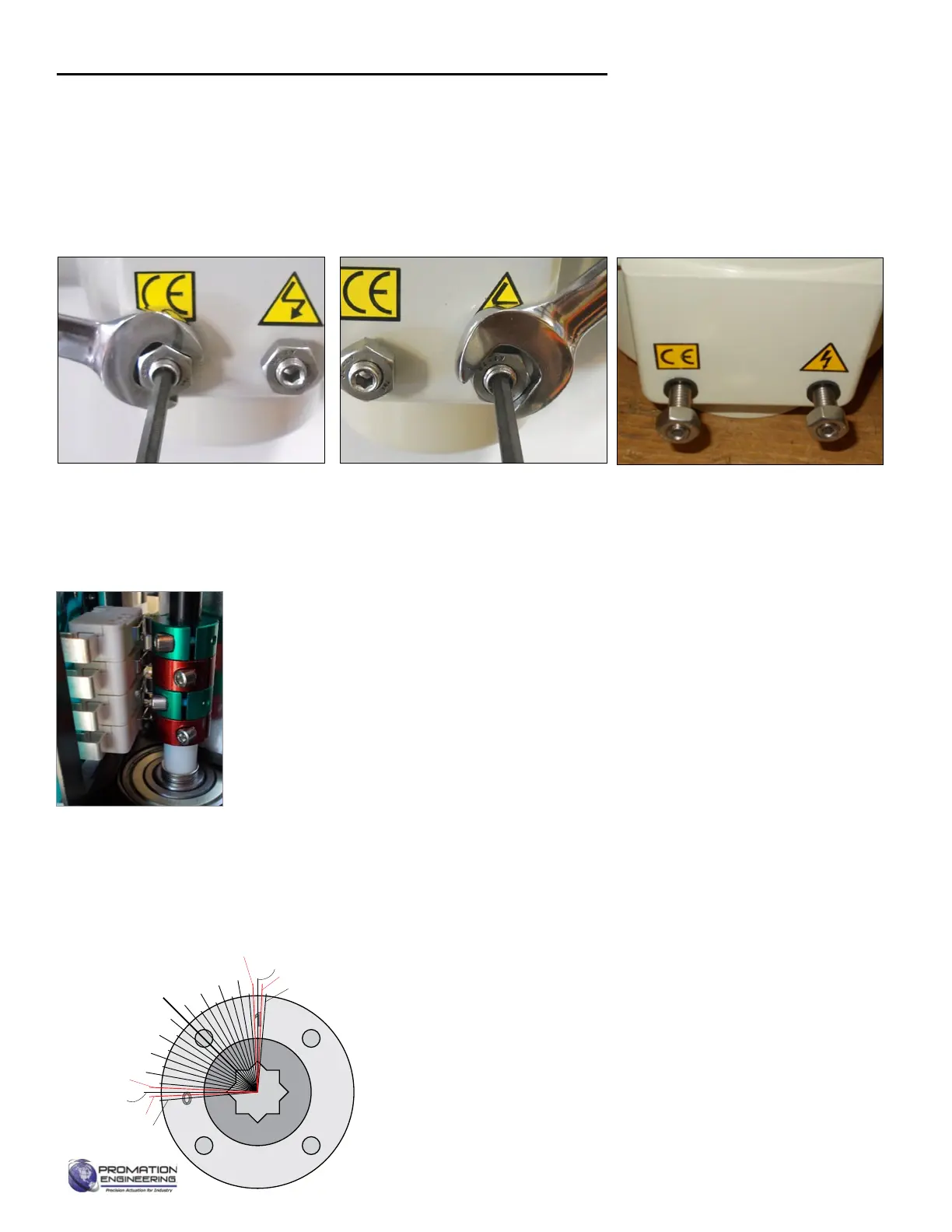
CW Mechanical Stop
CLOSE, 0°, 4mA, Red Cams
Mechanical Stop
Adjustment Positions
This actuator has been factory calibrated to operate between 0 degrees and 90 degrees. Proportional
Controllerpositioningchangesdierentfrom0and90degreeswilllikelyinvolvealsochangingcam
settings. If cam adjustments cause the controller board to show faults, you will need to reposition
the cam further outside your range of travel. Back out the mechanical stops before making any cam
setting change so the gear train does not strike a mechanical travel stop.
Serious Damage to the actuator will result if the motor is allowed to drive the gear train into
the mechanical stop!! Be sure the mechanical stops are out before making adjustments.
Cam 2
Cam 4
Cam 1
Cam 3
The mechanical stop screws limit handwheel operation ONLY and are NOT to be used as an electrical travel limiting device.
0
SW4 Aux Switch
SW2 CW Limit Switch
CCW Mechanical Stop
Controller CW
End of Travel
Controller CCW End of Travel
SW3 Aux Switch
SW1 CW Limit Switch
CW Mechanical Stop
10
20
30
40
45
50
60
70
80
90
Practical Cam Considerations
8. SW1 and SW2 can be used as electrical limit switches. For
proper function their cams must be set outside (or beyond) the
CLOSE and OPEN positions of the proportional controller.
9. SW1 and SW2 do not impact initial controller calibration unless
their cams are set within controller travel limits.
10. After changing any cam settings, test the actuator limits for
proper functionality.
CCW Mechanical Stop
OPEN, 90°, 20mA, Green Cams
Setting Limit Switches and Auxiliary Switches (Cams)
Page 6 of 17 P2/3 12V 24DC Proportional Series
FM_P28 24 PN4-DC Ver E 080223
 Loading...