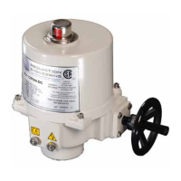
10. Set Loss of Signal (LOSS OF COMMAND LED is lit)
10.A Use▲ and ▼ to selectthefail position on loss of
signal. Select from the column right of the LEDs.
• CLOSE - fails close (4mA)
• OPEN - fails open (20mA)
• (BothO)-failsinplace(default)
10.B Press MODE to set
10.C AUX POSITION OUT CAL LED is lit.
The motor may drive an arbitrary position.
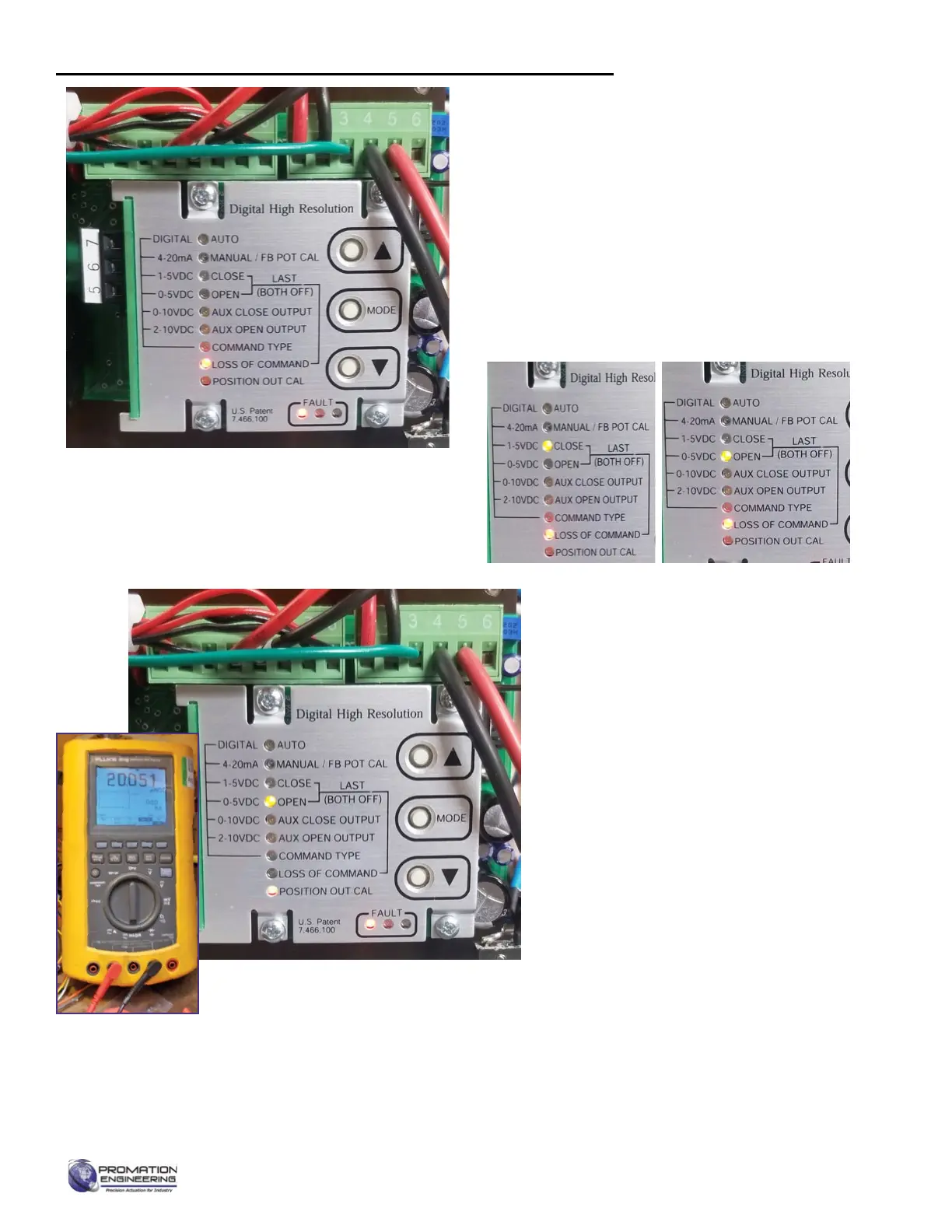
11. Trim the accuracy of the feedback (AUX
POSITION OUT CAL LED is lit)
11.A The position of the actuator is
unimportant for this step.
11.B CLOSELEDshouldbeflashing
11.C Use▲and▼toadjustthemAfeedback
for the CLOSE position (i.e. 4.00mA).
Read using a known accurate multimeter.
11.D PressMODEtoconrmsetting.
11.E OPENLEDshouldbeflashing
11.F Use▲and▼toadjustthemAfeedback
for the OPEN position (i.e. 20.000mA).
This isread on a known accurate
multimeter.
11.G PressMODEtoconrmsetting,
Calibrating the proportional control board (continued)
Page 11 of 17 P2/3 12 24 VDC Proportional Series
FM_P28 24 PN4-DC Ver E 080223
 Loading...