Contents
2 . . . . . . . . . . . . . . . . . . . Product Specifications
3 . . . . . . . . . . . . . . . . . . . Shipping and Handling
3 . . . . . . . . . . . . . . . . . . . Product Mounting and Setup
3 . . . . . . . . . . . . . . . . . . . Installation Notes
4 . . . . . . . . . . . . . . . . . . . Wiring Diagram
4 . . . . . . . . . . . . . . . . . . . Torque Switches
5 . . . . . . . . . . . . . . . . . . . Layout of Controller
6 . . . . . . . . . . . . . . . . . . . Check End of Travel Settings
6 . . . . . . . . . . . . . . . . . . . Status Indicators
7 . . . . . . . . . . . . . . . . . . . Adjusting the actuator CW position
8 . . . . . . . . . . . . . . . . . . . Adjusting the actuator CCW position
9 . . . . . . . . . . . . . . . . . . . Adjusting the actuator Auxiliary Switches
10 . . . . . . . . . . . . . . . . . . Mechanical Data
11 . . . . . . . . . . . . . . . . . . Mechanical Data
12-14 . . . . . . . . . . . . . . . Commissioning
15 . . . . . . . . . . . . . . . . . . AutoCalibration Procedure
IOM Template Master.indd
Page 1 of 17 P2/3 Series HV-TS AdVanced Proportional Control
FM_P213 ISO HV-PN4-HR (-TS) N7_Ver Q 080223
Page 1 of 18 P2-13 HV Proportion HR (-TS) Series
Field Manual
P7,8(S) HV-PN4-HR (-TS)
High Resolution Proportional Control
Powered Feedback
ISO5211 F12 8P36
Imperial Mount S 5in/6 BHC
P7 1.375in Shaft, 0.3125 in sq key
P8 1.625in Shaft, 0.375 in sq key
P
7
-
1
2
0
D
N
4
-
I
S
O
F
B
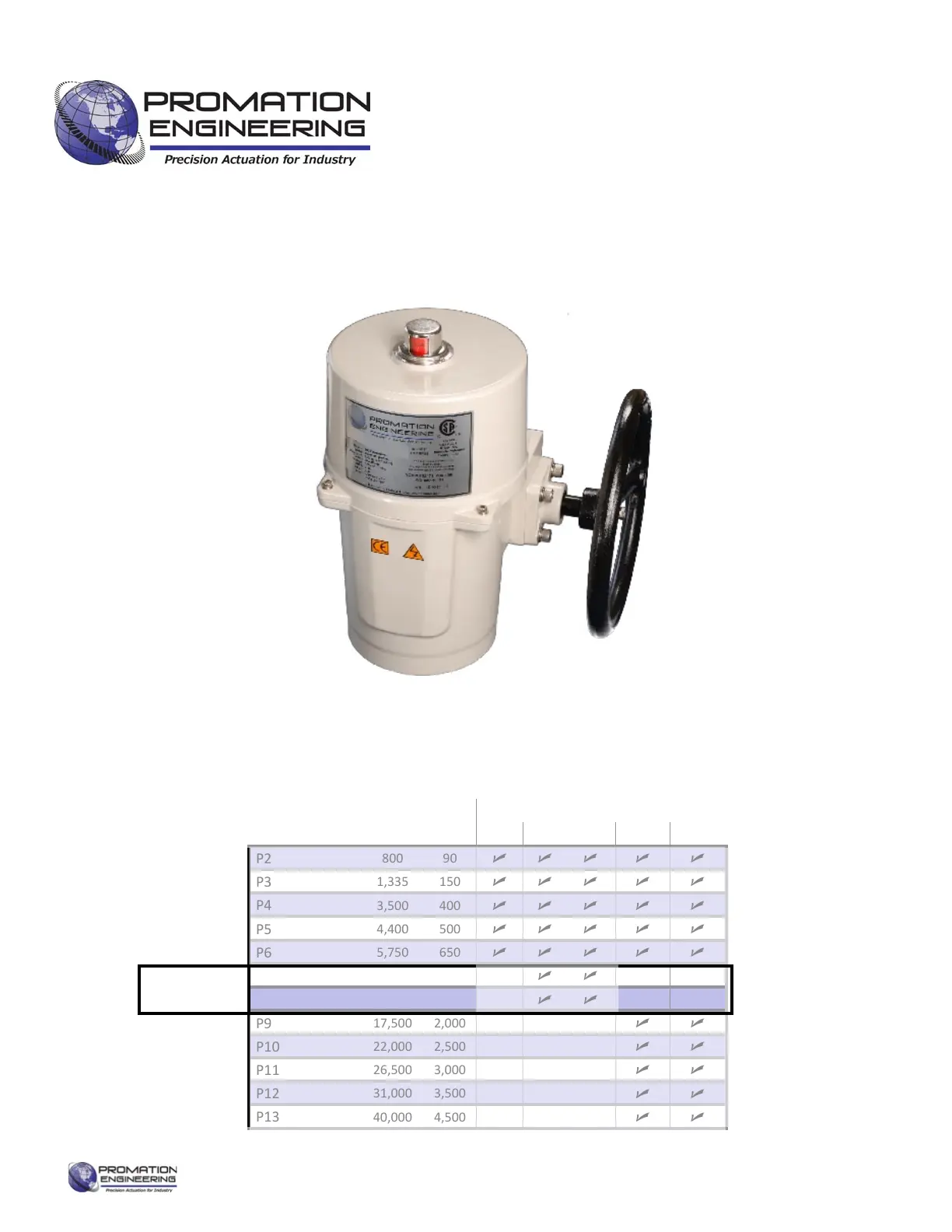
Product
Family
Torque Output Voltage Options
in lbs Nm 12DC 24DC 24AC 120AC 230AC
P2
800 90
P3
1,335 150
P4
3,500 400
P5
4,400 500
P6
5,750 650
P7
8,900 1,000
P8
13,250 1,500
P9
17,500 2,000
P10
22,000 2,500
P11
26,500 3,000
P12
31,000 3,500
P13
40,000 4,500
Actuator Sizes and Voltage Opons
Actuators In
This IOM
ISO 5211 Mount Shown
 Loading...