FM_P213 ISO HV-PN4-HR (-TS) N7_Ver Q 080223
1. This actuator is shipped in the FULLY CW position (2 color position indicator
shows “CLOSE” and the Reference Dimple aligns with “0”).
2. NOTE, THIS ACTUATOR MUST HAVE WATER TIGHT EMT FITTINGS, WITH
CONDUIT DRAINAGE INSTALLED AND POWER SUPPLIED TO UNIT TO
KEEP THE HEATER WARM AT THE TIME OF INSTALLATION.
3. Storage: This unit should NOT be stored outside unless it is powered up
and has proper conduit terminations. When NOT powered up, it should be
stored in a clean, dry environment at all times.
4. This actuator has been factory calibrated to operate between 0 degrees and
90 degrees. Most quarter-turn products will not require recalibration of
these settings. If any travel adjustment is necessary, please refer to page 10.
Cam adjustments instructions, pages 6-7 are included for reference only -- the
proportional controller should be used for any changes to positioning.
5. The actuator CANNOT operate with a rotation greater than
95 degrees.
1. Fully CLOSE the valve or damper to which the actuator is to be mounted.
• Keep in mind this actuator rotates CW (as viewed from above the unit) when driving CLOSED.
2. Assemble necessary linkage components and attach the actuator to the driven device.
3. Tighten mounting bolts, making sure actuator is centered on the device drive shaft.
4. Utilize the handwheel to check for unobstructed manual operation from fully CCW to fully CW positions BEFORE
applying power to the unit.
5. Make the electrical connections per wiring diagram on page 4.
• Connect POWER to terminals marked 1 and 2 on the switch card (430-10100).
• ConnectCONTROLto(DHC-100J2)terminalsmarked4and5OR4and6perWiringDiagramonpage4.
• Terminals 7-12 on the switch card (430-10100) can be used for the (adjustable) aux switches. They are dry type
Form C rated 10A @ 250vac MAX.
6. Do NOT apply power at this time.
• These actuators are designed to be used between a horizontal and upright
position. Do NOT mount the assembly with the actuator top below a horizontal
position.
• When installing conduit, use proper techniques for entry into the actuator. Use
drip loops to prevent conduit condensate from entering the actuator.
• Mechanical travel stops are factory calibrated for 90 degree operation. These
stops are NOT designed to adjust mechanical rotation by more than +/- 3
degrees, they are for positioning the handwheel only.
• Both NPT conduit ports MUST use proper equipment to protect the NEMA 4X
integrity of the housing.
• The internal heater is to be used in ALL applications.
• Do NOT install the actuator outdoors or in humid environments unless it is
powered up and the heater is functioning.
• Use proper wire size to prevent actuator failure (see chart on page 4 for proper
wire sizing).
• All terminals accept 12-16AWG solid/stranded wire.
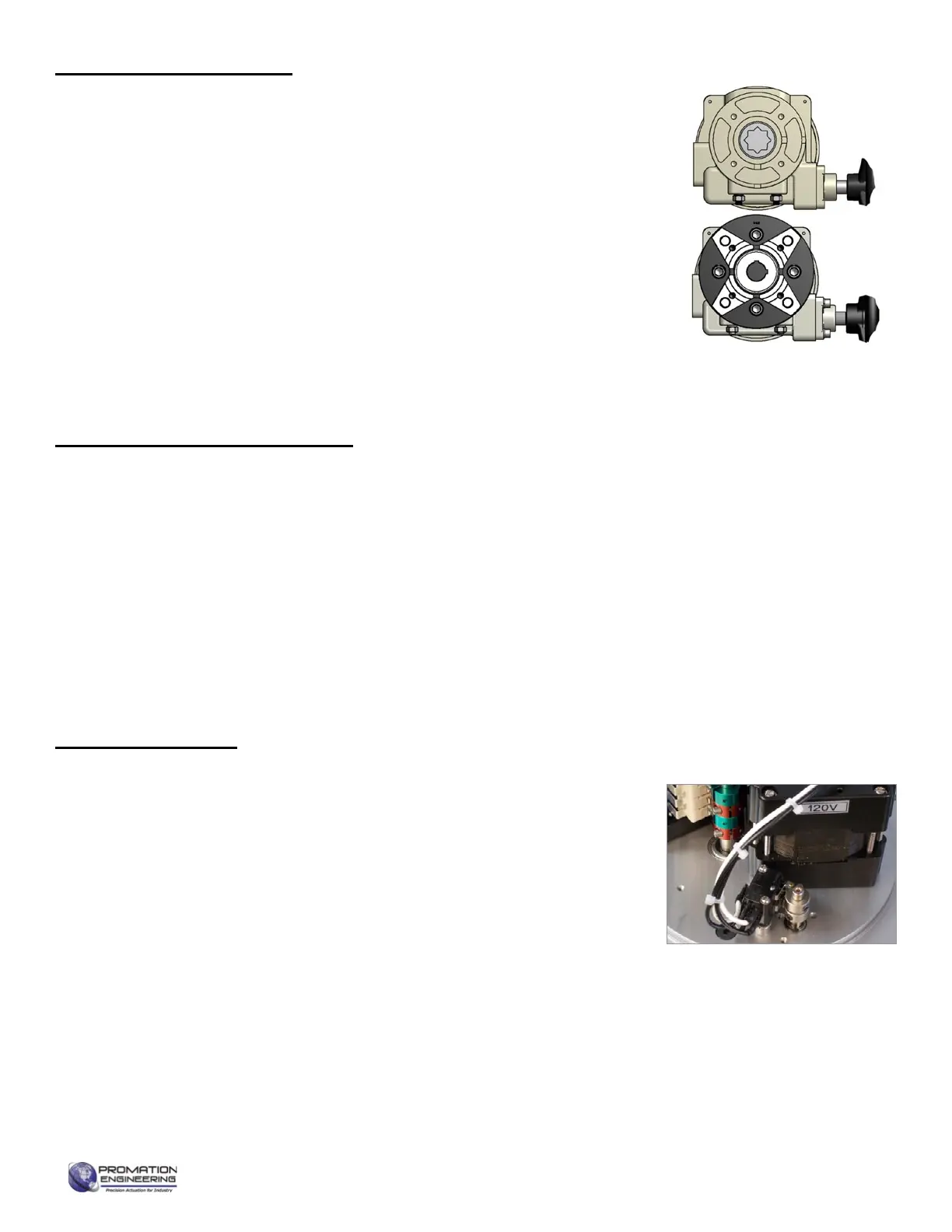
Identifying Torque Switch Units:
• -TS in Product Name on label.
• Units with Torque Switches have
additional switches mounted on
the motor plate (see photo).
Page 3 of 18 P2-13 HV Proportion HR (-TS) Series
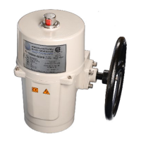
ISO
Imperial
Shipping and Handling
Product Mounting and Setup
Installation Notes
 Loading...