TECHNICAL DATA
• Dimensions Height – 250mm
Width – 285mm
OPERATION INSTRUCTIONS
• The Propex Malaga 5 is for use on L.P.G. only.
Malaga 5E is for use on both L P G and mains electricity
• Weight empty 9.3kg
• Nominal Water capacity 13 Litres
• Inward protrusion from wall 480mm
• HEATING TIMES Gas Approx. 43 Mins
15
o
C– 70
o
C Gas & Electric Approx. 28 Mins
On initial operation or when the system has been drained, refill the system with
water and flush out by turning on each hot tap until a steady flow of water is
obtained. If a water filter is fitted it should be changed at the recommended
intervals.
Approx. 64 Mins
• Standby consumption Gas 98W
• WATER - Maximum supply pressure 1.3 BAR
Pressure relief valve setting 3.0 BAR
Working pressure 2.0 BAR
•
Check that all the gas and electricity supplies are turned on.
GAS – Switch to the gas position on the control panel. Initially no LED will come
on and there will be a 10 second delay. Ignition will then take place and the green
LED will stay on as long as the burner is alight. If the gas does not light first time,
Injector Bray 960 / 40
Gas connection 8mm / 5/16 o.d.
Gas type Butane 28-30mBAR
Propane 37mBAR
Pressure category & pressure I
3+
(28-30/37)
delay before it tries again.
Note – When the water has reached the preset temperature the green LED will
switch off. As the water cools or is drawn off, the heater will automatically start
the above sequence again. If the red LED starts flashing it indicates a fault
condition
• ELECTRICITY –Malaga 5 12V DC
Malaga 5E 12V DC + 230V AC element
Element 750W
Current consumption @ 12V 0.36A
ELECTRICITY – The Malaga 5E has a 230V, 750W immersion heating
element. The operation of the immersion heater is controlled by the same
thermistor that controls the gas burner. If you wish to use the immersion heater
operate the 230V switch on the control panel. The immersion heater can be used
Note: If connecting to mains water supply, a suitable water pressure regulator
must be connected to ensure that the maximum supply of water pressure
does not exceed 190kPa (1.9bar)
Clearances required for installation and servicing, as seen from the inside.
Left Hand Side 240mm
Ri
time.
Note – A 12V DC supply must be connected at all times.
SWITCHING OFF THE APPLIANCE – If the appliance is not in use it should
When not in use the
Top 5mm
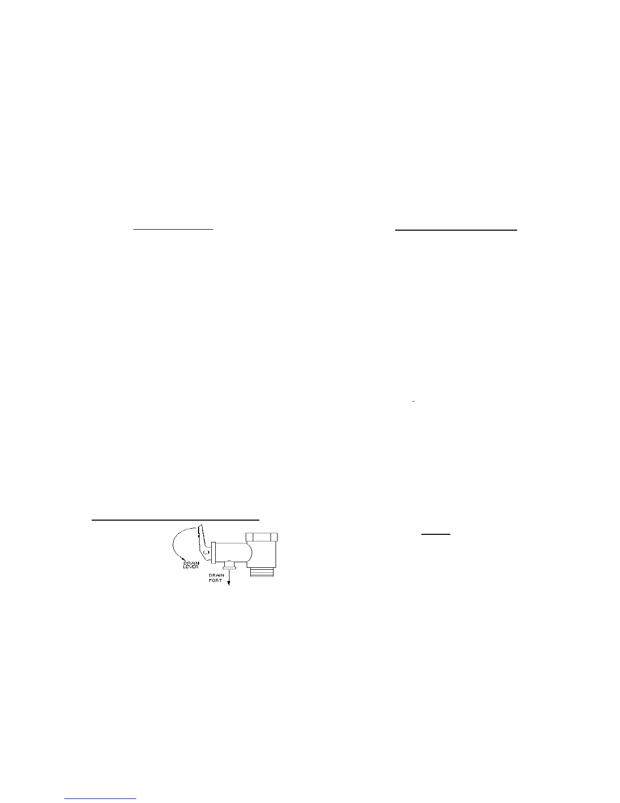
PRESSURE RELIEF/DRAIN VALVE
e switched off using the control
a
long period of time the tank should be drained and gas supply isolated.
WATER – This appliance must not
be connected directly to the mains water
supply.
heater should be drained
using the drain valve as
per the diagram.
- 10 -
BATTERY – The heater is designed to operate on a 12V DC supply. Should the
supply drop below 10V or rise above 15V, the gas valve will switch off and a
fault code of 3 flashes will be displayed on the control panel.
-3 -
 Loading...