CONNECTING THE WATER HEATER
When installing a non return valve should be fitted if necessary.
1. WATER: The Malaga 5 is fitted with 12mm plain stems to which a suitable
INSTALLATION INSTRUCTIONS
A competent person should install the appliance in accordance with the
appliance installation instructions and should consider any relevant
mm I.D. reinforced, food quality, opaque or equivalent pipe with hose clips. It is
important that the hot and cold connections are connected correctly and if the
plastic inlet connection is removed, only a plastic replacement should be used.
IMPORTANT: The hot water outlet connection at the top of the tank must not
appliance in Europe the standard is BS EN 1949:2002 (Specification for
the installation of LPG systems for habitable purposes in leisure
accommodation vehicles and in other road vehicles).
Installation and servicing of this appliance must only be carried out by
istered with the Gas Safet
r
space for expansion inside the tank. The water pressure must not exceed 1.3 bar.
ALSO do not connect this appliance to a mains water supply.
Drain/Pressure Relief Valve – Drill the appropriate sized hole in the floor
close to the heater and run a piece of hose from the drain port, through the hole
national organisation.
Prior to installation check the compatibility of the data plate information
with the LPG supply requirements of the vehicle.
This appliance must be installed in accordance with the current regulations.
to the outside. Seal round the hole with silicone o
.
Water Systems – The heater will work satisfactorily on either system where the
pump is controlled by a tap, micro-switch or pressure switch.
2. GAS: The gas fitting is 8mm (5/16”) and a suitable compression fitting is
required. An isolation tap should be fitted near to the heater and any
Pt 1 1978, BS5482 Pts 1 & 2 1977 and BS5440 Pt 2 1990.
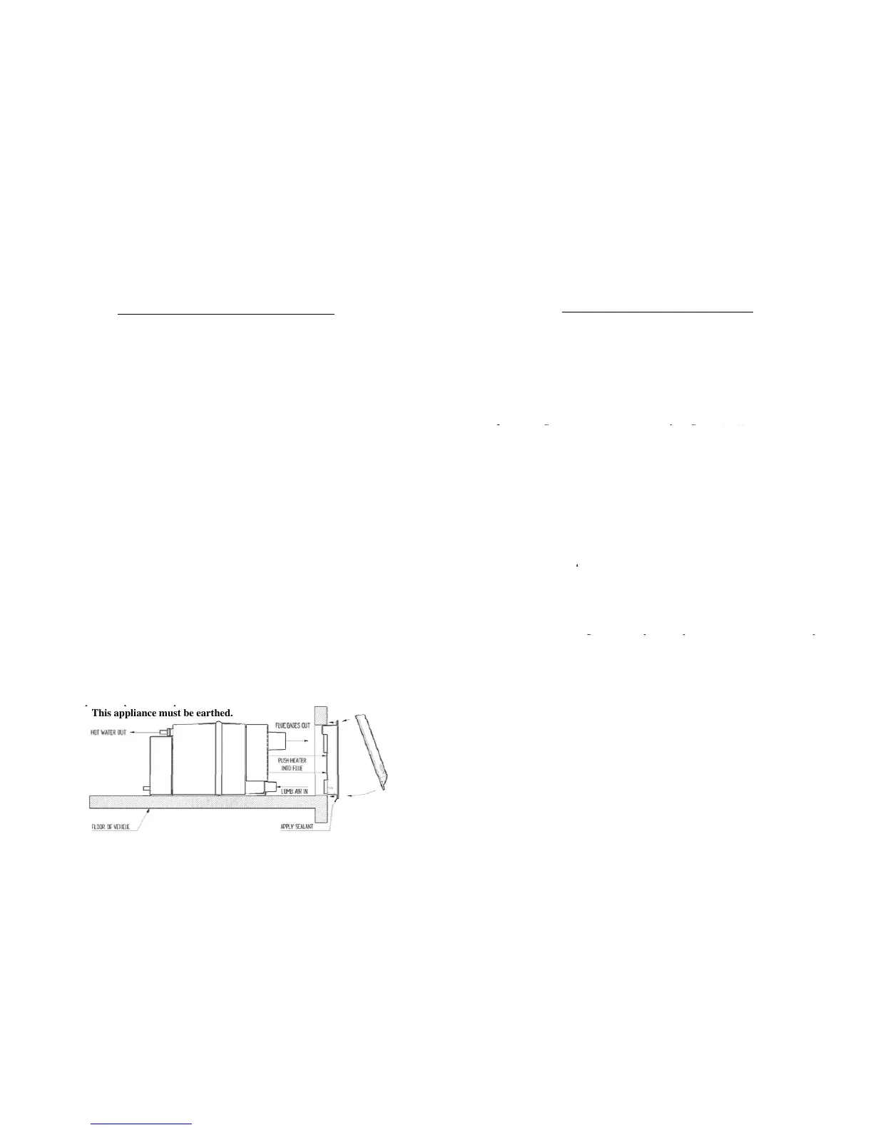
The Malaga 5 Water Heater is designed to be floor mounted and flues
through a vertical section on an external wall. Normally the heater would be
fitted in a bed-box or locker allowing access to the heater with suitable room
fo
ection. Structural sections within the vehicle shoul
e
positioned near to the heater and that all connections are carried out by a
registered person (see Installation section on page 3) .
3. ELECTRICITY: Fit the control panel in the chosen position and route the
loom down to the heater and plug into the PCB at CN27 & CN26. Connect the 2
be damaged. The flue terminal should not be fitted at the side of the
caravan/motor home where an awning may be fitted.
FLUE – Using masking tape, fix the template to the inside of the vehicle and
drill a pilot hole at position X. Remove the template and tape it to the outside
of the vehicle ensurin
polarity is correct. NOTE there is one less core on the loom used on the Malaga
5 and is supplied with a single on/off switch, whereas the Malaga 5E has 2 x 2
position switches to allow independent operation of gas or electric.
Malaga 5E only – The 3 core mains cable should be connected to a 230V AC –
5am
with the hole drilled from the inside.
Drill a 10mm hole at positions A and, using a jigsaw, cut out the hole. The
hole in the wall must be battened to secure inner and outer skins.
Note: When battening the finished hole must be 240mm x 135mm. Run a
bead of silicon rubber, or similar sealant, around edge of the rear side of the
Note: This appliance must be earthed.
¾”) provided and remove excess sealant. Clip the top of the flue cover onto
the flue terminal and secure with 2 screws (No. 6 x ½”) provided.
WATER HEATER – Remove the floor covering (e.g. carpet etc) from the
area where the heater will stand – 450mm inward from the wall and 320mm
vehicle. Slide the heater through the flue seals until the stop position is
reached. Make sure both flue and air intake pass through the lip seals.
Measure 115mm from right hand side of rear foot and line up with line on
floor – screw heater to the floor.
-5 -
 Loading...