The Protec Algo-Tec™ 6400 is an interactive digital addressable fire control system designed for comprehensive fire detection and management in various environments. This quick operating guide provides essential information for users to effectively monitor and respond to fire and alarm events.
Function Description
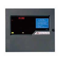
The Algo-Tec™ 6400 system serves as the central hub for fire detection, monitoring, and control. It supports 1 to 4 loops, allowing for extensive coverage and integration of numerous fire detection devices. The system continuously monitors all connected devices for fire activations, faults, and disablements. Upon detecting a fire signal, it initiates a series of actions including audible alarms, visual indications, and the display of detailed event information on its LCD screen. The system is designed to provide clear and immediate information to building occupants and emergency services, facilitating prompt evacuation and response. It also manages control outputs, which can be programmed to activate various plant equipment or other safety systems in the event of a fire.
Usage Features
The control panel features a user-friendly interface with an LED display, an LCD display, control buttons, a QWERTY keypad, and arrow keys for navigation.
-
Viewing Fire / Alarm Events:
- Upon a fire alarm, the panel's audible buzzer will fast pip, the 'FIRE' lamp will illuminate constantly, and the 'ZONE' location lamp will illuminate intermittently.
- The LCD display will show detailed information about the fire event, including the zone number, node, loop, address, and type of the device in alarm. If text has been assigned to the node, this text will be displayed instead of the node and loop number.
- The display also shows the date and time of activation, the number of devices currently in alarm, and any existing fault events or disablements.
- In the event of a fire, the primary actions are to evacuate the premises immediately, send for the fire brigade, and not re-enter until authorized.
-
Sound Alarms:
- The red 'SOUND ALARMS' button can be pressed to activate pre-programmed alarm outputs.
- Pressing this button will illuminate the 'Alarms On' LED, cause the buzzer to fast pip, and display "SYSTEM STATUS: SOUND ALARMS" on the screen. This ensures that all programmed alarm outputs on the network are activated as commissioned.
-
Silence Alarms:
- The 'SILENCE' button is used to silence all 'Alarm outputs' on the network after a fire event.
- Pressing this button will cause the 'ALARMS SILENCED' LED to illuminate or the Silence logo to appear on the LCD.
- It's crucial not to attempt to 'RESET' the system at this stage until the cause of the fire has been established. The fast pip indicates that external alarm outputs are still active.
-
Accept Events:
- The 'ACCEPT' button allows users to acknowledge any fire or fault events and mute the fault buzzer. This helps in managing multiple events and ensures that new events are not missed.
-
Resetting Fire Events:
- After silencing alarms and establishing the cause of the fire, the 'RESET' button can be pressed.
- This action will extinguish all fire indications, reset any plant equipment (control outputs), and clear the system.
- If an automatic detector or manual call point remains active, the fire condition will re-start.
-
Display of Fault Events:
- If a fault appears on the system, the panel buzzer will sound intermittently, and the 'FAULT' LED will illuminate.
- The LCD will display the number of faults that need to be viewed, allowing for quick identification and resolution of issues.
-
Printing Fire Events:
- The 6400 control panel does not automatically print fire events. Instead, events are printed on demand.
- If there are pending events, a 'Print Pending Icon' will be shown on the top right corner of the LCD display.
- To print these events, the user needs to press and hold the 'Fn' key and then press the 'p' key on the QWERTY keypad.
-
Control Buttons: These buttons provide direct access to critical functions, simplifying operation during an emergency.
-
QWERTY Keypad and Arrow Keys: These are used for navigating menus, entering data, and interacting with the system's advanced features.
-
Numeric Keypad: Provides a convenient way to enter numerical data, such as access codes or specific addresses.
Maintenance Features
While the quick operating guide primarily focuses on immediate response, the system's design inherently supports maintenance activities through its fault reporting and event logging capabilities.
- Fault Indication: The system continuously monitors for faults and provides clear indications on the LCD and through the 'FAULT' LED. This allows maintenance personnel to quickly identify and address issues, ensuring the system remains fully operational.
- Disablements: The system tracks and displays any disablements, which are temporary deactivations of specific devices or zones. This feature is crucial for planned maintenance, allowing technicians to work on parts of the system without triggering false alarms, while still being aware of which areas are temporarily out of service.
- Event Logging: Although not explicitly detailed in this quick guide, the ability to print fire events implies an internal event log. This log is invaluable for post-event analysis, troubleshooting, and routine maintenance checks, providing a historical record of all system activities, alarms, faults, and user interactions. This helps in understanding system behavior over time and planning preventative maintenance.
- System Status Information: The LCD provides real-time status updates, including the number of devices in alarm, faults, and disablements. This comprehensive overview helps maintenance personnel assess the overall health of the fire detection system at a glance.
The Protec Algo-Tec™ 6400 is designed to be a reliable and intuitive fire control system, providing essential tools for both emergency response and ongoing system management. For a complete understanding of all features and detailed maintenance procedures, users are directed to the full operating manual available on the Protec website.