92-26177-555-01
Page 2 of 6
5. Remove the grounding screw securing the main furnace control board (IFC) to the mounting plate.
Note: This screw will not
be used with the replacement control board (IFC). Instead, a ground wire (to
be installed in a later step) takes the place of this screw.
6. Before removing control boards, note dip switch positions to be transferred to the replacement control
(IFC). Replacement should match the old control. Some particularly critical functions (such as cooling
airflow) must be transferred to the replacement by duplicating the dipswitch selections. (See furnace
installation instructions for details and dipswitch assignments). Further, some dipswitch selections have
been replaced in the new control with jumpers. The jumpers are intuitive and clearly labeled. (Note:
When using a two-stage thermostat with 2 heat speeds, the jumper at J5 should be set to the “None”
position (factory default). When using a single-stage thermostat with 1 heat output, and expecting the
timed staging feature, the jumper at J5 must be set to either 5 (five minutes) or 12 (twelve minutes)
according to the customer’s preference. The five or twelve minutes refers to the amount of time the
furnace remains in low heat before automatically switching to high-fire heat.) See Appendix A at the
end of these instructions for additional information regarding dip switches.
7. Remove existing control board by squeezing the locking tabs of the white mounting feet so that the
control can be pulled free from the mounting feet.
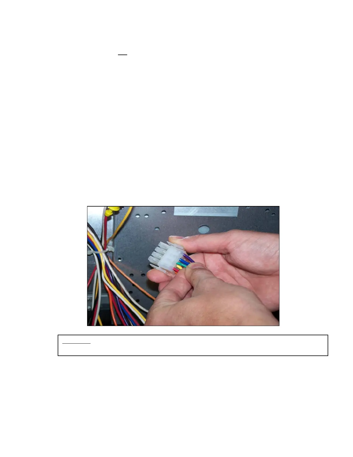
8. Insert green wire spear connector assembly (AS-50208-31-CY) into position #9 of the 12 pin Mate-N-
Lok style connector which plugs into the main furnace control board (IFC) at position P-1. The pin end
snaps directly into position #9 (See Figure 1). Position #9 is the only open position on the plug with no
wire inserted into it. Route the opposite end (with eyelet) of this green wire to the green grounding lug
in the junction box as indicated
9. Remove the main power junction box cover.
10. Remove the cover of the junction box and remove the grommet from the back side of the main junction
box (see Figure 2).
FIGURE 1: INSERT THE GREEN WIRE SUPPLIED WITH THE REPLACEMENT CONTROL INTO
POSITION #9 OF THE 12-PIN MATE-N-LOK STYLE CONNECTOR.
 Loading...