92-26177-555-01
Page 3 of 6
11. Run the green wire through the hole in the back of the junction box where the grommet was.
12. Reinstall the grommet.
13. Attach the other end of the green wire assembly to the grounding screw inside the junction box using
the eyelet (see Figure 3). Make sure that the system ground wire (which exits the furnace) is also still
attached to the ground screw. Also, it is critical that the ground wire exiting the furnace is attached to a
proper earth ground. Replace the cover of the junction box.
FIGURE 2: REMOVE THE GROMMET FROM THE BACK SIDE OF THE JUNCTION BOX.
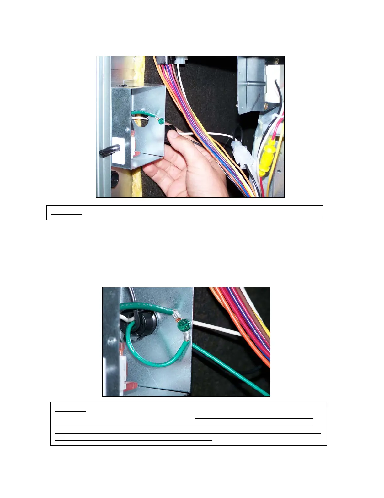
FIGURE 3: MAKE SURE THAT BOTH GREEN GROUND WIRES ARE INSTALLED TO THE
GROUNDING SCREW IN THE JUNCTION BOX. NOTE: WITHOUT NEW GROUND WIRE,
FURNACE WILL NOT FUNCTION AND “STATUS” LED WILL INDICATE A FAULT CODE
BY BLINKING 6 TIMES. THIS FAULT INDICATES THE GROUND WIRE IS NOT INSTALLED
OR THAT LINE (L1) AND NEUTRAL ARE REVERSED.