ENGLISH
HEIGHT OF INSTALLATION
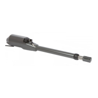
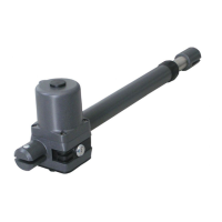
Ace TI operators (version with inox tube).
MECHANICAL STOPS (Fig. D)
EXTERNAL OPENING GATE
BRACKETS S2 (Fig. F)
Calculate the height of the installation of the actuator according to the gate's shape and
to the possibilities of fastening. (Fig. G) Determine the position of bracket S3 as follows:
a) If the gate has a big structure you can put the actuator at any highness with no limits. - Close the gate's wing.
b) If the structure is light it is necessary to keep the actuator the nearest possible to the - Rotate anticlockwise the actuator's end, that is to say its final part (piece n.35 in the
middle of the gate (in height). list of parts) until the end-of-stroke position of the rod (until the rod is completely
Position 1 Central beam of the gate out), then rotate the end of the actuator clockwise until the fixing screw of the end is
Position 2 Stiffen of the gate down-sided. In any cases, the final part of the actuator must be rotated at least of
half a turn.
FIXING OF BRACKETS S1/S2 - Fasten bracket S3 to the end of the actuator as indicated in “Fig: M” keeping in mind
Bolt or weld the bracket S1 or S2 on the gate's side pillar, keeping in mind that the that the threaded hole of the rotation pivot PR1 must be turned down.
measures A and B refer to the gate hinges axis and to the actuator's rotation axis. - Position the actuator on the gate's wing keeping it levelled and mark the position of
In case of fastening by expansion bolts, use Ø 13 mm metal bolts and place the bolt at no bracket S3 on the gate.
less than 30÷35 mm from the pillar's corner, to avoid breaking of corner. (Fig. H) - Weld or bolt bracket S3 to the gate.
In case of masonry pillars, use chemical or resin bolts or stone the bracket.
- Be careful in using bracket S1 (Fig. E) which is in two versions: bracket S1 right
end bracket S1 left, they should be used with their actuator; left or right. At this point you need to position the mechanical stops: first the wing's stop in closing
- Fasten the actuator to bracket S1 as indicated in “Fig. I”, please pay attention that and then in opening phase.
the threaded hole of the rotating pivot PR1 must be turned down.
In case of external opening gate is possible to place the actuator on the internal side.
In this case the measure A (distance between the axe of the hinges and the rotation axe
of the actuator) has to be measured towards the centre of the gate, and it is necessary to
Each bracket is made up of 1 a squared plate, dimensions 130x130x6 mm, with 4 holes
modify the bracket S2 to adapt it to the new fixing position. (Fig. N)
of Ø12 mm and 1 bracket 112x94x55 mm with 3 holes of Ø 12 mm.
In order not to reduce the length of the passage, the actuator can be positioned in the
How to fix brackets S2:
superior part of the gate, at a height not inferior to 2 m.
- Screw the plate to the pillar using strong bolts.
You can find the position of the front bracket with the method indicated above, but with
- Weld the bracket to the plate as indicated in Fig. F
the wing of the gate open.
Remember that the measures A and B refer to the gate hinges axis and the operator's
Due to the motor's power, all fastenings must be very strong
rotation axis.
HOW TO RELEASE THE OPERATOR
FIXING OF FRONT BRACKET
- Insert the key (supplied in the kit) and rotate it clockwise of 90°. (Fig. S)
Ace TA operators (version with alum. tube).
-
Determine the position of bracket S4 as follows:
- Close the gate's wing.
- Release the actuator.
- Move forward the front pivot of the actuator until it reaches the position of limit switch
in opening .
Leave 20mm of space between the pivot and the actuator end. (Fig. L)
- Fasten bracket S4 to the front pivot of the actuator as indicated in “Fig. M” keeping
in mind that the threaded hole of the rotating pivot must be turned down and that the
dragging pivot milling must be placed longitudinally to the hole. (Fig. P)
- Put the actuator on the gate's wing keeping it levelled and mark the position of
bracket S4 on the gate.
- Weld or bolt bracket S4 to the gate.
- Control that the drag pin has been positioned with the two sides of the milling in
parallel position to the button hole of the alum. tube as indicated in the “Fig. Q”.
In case of particular installations it is advisable to use brackets S2
Pull the left motor's release handle towards the interior, pull the right motor's release
handle towards the gate.
.
 Loading...