Do you have a question about the Proteco Q60S and is the answer not in the manual?
Details the external radio panel and its connection to the main unit.
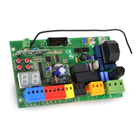
Identifies and briefly describes key components of the control unit.
Guides users on navigating and modifying control unit parameters.
Explains the visual signals displayed by the unit during operation.
Describes the purpose and self-restoring nature of the 24V fuse.
Overview of parameter modes like PA, FA, DE, and AS for operation.
Details functions for managing remote control codes.
Lists key operational times and their standard default values.
Crucial step to delete existing codes before first-time radio programming.
Instructions for programming DIP-switch and HIT type transmitters.
Procedures for displaying, erasing single, and erasing all stored codes.
Process for acquiring and storing new remote control codes with function options.
Pre-commissioning warning regarding limit switch type selection.
Illustrative example of adjusting the motor working time parameter.
Detailed step-by-step explanation of the standard programming process.
Detailed step-by-step explanation of the sequential programming process for sliding gates.
Indicates a failure during the photocell test procedure.
Problems with photocell or safety edge during opening or closing phases.
Indicates a limit switch problem in either the opening or closing phase.
Faults due to short circuits or wiring in start or pedestrian signals.
Indicates that the stop button has been pressed.
Indicates motor issues or radio continuous transmission.
Configures automatic closing behavior, including stop/reverse on impulse.
Controls command acceptance during the opening phase for multi-user mode.
Instructions for connecting motor and network cables to earth terminals.
Details connections for start, stop, photocell, safety edge, and radio receiver.
Details motor output connections and capacitor placement.
Details power input and accessory power supply connections.
Wiring diagrams for start and pedestrian start inputs.
Wiring diagrams for permanent start command and emergency stop button.
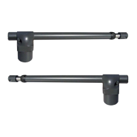
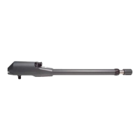
Wiring diagrams for electromechanical motor and limit switches.
Schemes for motor wiring on right/left side and gate closing direction.
Diagrams illustrating the correct fixing positions for magnetic limit switches.
Wiring schemes for motor and limit switches on the left gate side.
Diagram and instructions for connecting photocells in the closing phase.
Diagram and instructions for connecting photocells in the opening phase.
Wiring for motors and limit switches when used with a road barrier.
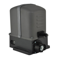
| Lifting Capacity | 600 N |
|---|---|
| Voltage | 230 V |
| Battery Backup | Optional |
| Warranty | 2 years |
| Speed | 0.2 m/s |
| Safety Features | Obstacle detection |
| Remote Control | Included |