1 2
3 4 5 6
7 8
9
10 11
12
1 2
3 4 5 6
7 8
9
10 11
12
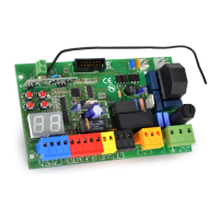
6 CONNECTING PHOTOCELL IN CLOSING PHASE
CONNECTING PHOTOCELL IN OPENING PHASE
4 - 9: Link terminals 4 and 9 if the photocells are
not used in the opening phase.
PHOTOCELLS CONNECTIONS
8 = Power supply + PHOTO RX
9 = Power supply + PHOTO TX
10 = Power supply - COM. PHOTO TX/RX
4 - 8 = Connections photocells
Linkterminals4-9
Terminalblock2
3 - 9: Link terminals 3 and 9 if the photocells are
not used in the closing phase.
PHOTOCELLS CONNECTIONS
8 = Power supply + PHOTO RX
9 = Power supply + PHOTO TX
10 = Power supply - COM. PHOTO TX/RX
3 - 8 = Connections photocells
Linkterminals3-9
Terminalblock2
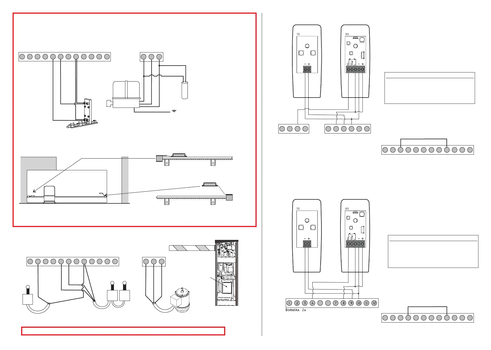
MOTOR AND LIMIT SWITCH WIRING IN CASE OF USE WITH ROAD BARRIER
RIGHT
controlunit
FC
STOP
FC
AP
FC
CH
1 2
3 4 5 6
7 8
9
10 11
12
N.B. : TO REVERSE THE OPENING SIDE PLEASE SEE THE BARRIER INSTRUCTION MANUAL
BLUE
BLUE
BROWN
BROWN
13 14
15
BLUEORGREY
BROWN
BLACK
BLACK
LOW bracket for magnetic limit on the
LEFT SIDE of the gate (closing function)
HIGH bracket for magnetic limit on the
RIGHT SIDE of the gate (opening function)
BROWN
CAPACITOR
YELLOW/GREEN
BLUE+ORGREY
Terminalblock3Terminalblock2
13 14
15
WIRING SCHEME FOR MOTOR ON THE LEFT SIDE AND GATE CLOSING RIGHT
(inside view)
MOTOR WIRING
1 2
3 4 5 6
7 8
9
10 11
12
Red
Red
Red
Red
BLACK
BLACK
BLACK
MAGNETIC LIMIT SWITCHES FIXING
Bornera2a
1 2
3 4
7 8
9
10 11
12
1 2
3 4
7 8
9
10 11
12
5 6