Action Check
Connect the unit to 230/130/115VAC + Earth.
It will take the unit 10-45 min. to warm up to operating temperature.
Check that the phase and neutral wires are connected correctly.
1
9
2
DIS
Connect the DISABLE signal to the RELAY terminals on relay. Connect
12V Output to to PS IN ”+” and ”-” on relay.
When the alarm is set (armed) the 12V signal must be removed.
Check correct polarity +/–.
When the alarm is disarmed, a ‘d’ must be shown in the display. When
the alarm is armed, the ‘d’ must disappear (input dead).
3
PRIM
Connect the PRIMARY signal to the RELAY terminals on relay. Connect
12V Output to to PS IN “+” and “-” on relay.
If the alarm signal is closed in the event of a burglary DIP 6 is set to
ON (recommended). If alarm signal is opened, DIP 6 is set to OFF.
In the event of an alarm signal, a ‘P’ must be shown in the display. In
the event of malfunction, check that 12 V in and out is working and
that DIP switch 6 is set correctly.
4
SEC & ARM
These inputs are not normally used with Ajax. Set DIP 5 and 7 to OFF.
If the alarm signal is closed in the event of a burglary DIP 6 is set to
ON (recommended). If alarm signal is opened , DIP 6 is set to OFF.
Check that “A” and “S” are shown in the display.
5
The unit is ready for testing when it is fully warmed up.
Remember to set a fog time on the DIP switches 2, 3 and 4.
The display will scroll continuously, typically:
H-r-d-A-P-S-bAt-bt-norc-c (see meanings in the manual).
In order to re a fog, the following must be displayed:
r-A-P-S.
Meaning:
r- The unit is warm
A-P-S All triggers are active and DIS (d) is not blocking the
machine.
6
Before you nish the installation, also consider the need and method
of connecting the outgoing signals. The diagram on the reverse page
only shows the principle of the relay connections.
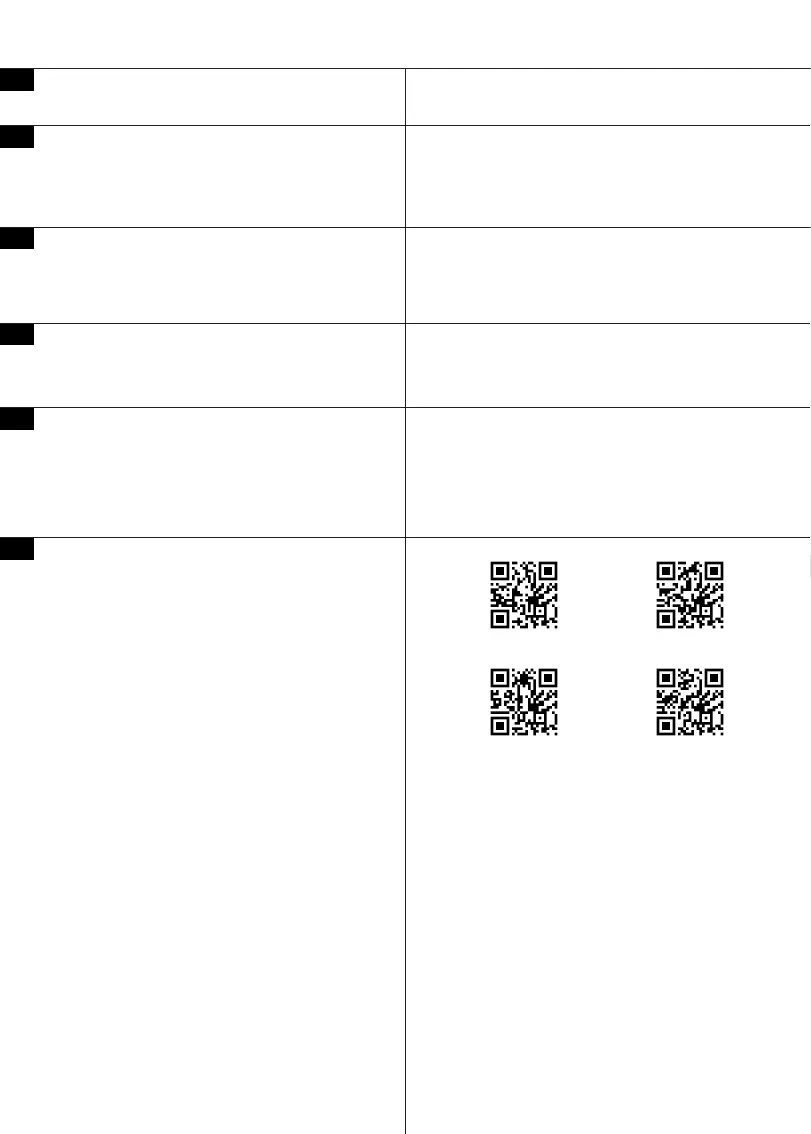
Outgoing feedback option. MultiTransmitter - Use PROTECT
MultiCard™ expansion card to provide most Status and Error codes
via Ajax MultiTransmitter.
Outgoing feedback option. IntelliCloud™, free cloud based feedback
- use PROTECT IPCard™ expansion card to provide feedback via
smartphone or PC. Internet connection required via RJ45.
Outgoing feedback option. Use Ajax wireless output relays, eg: door
contacts to provide.
Tamper circuit is not shown. The Fog Cannon has a normal tamper
switch, which can be integrated in a usual tamper circuit (additional
relay required).
Always remember to make a full scale test to check that, the alarm
system, fog security system and PIR sensor are working together
and to ensure that the amount of fog will cover the secured area as
expected.
PROTECT MultiCard™ Ajax MultiTransmitter
PROTECT IntelliCloud™ PROTECT IPCard™