Supplied By www.heating spares.co Tel. 0161 620 6677
12
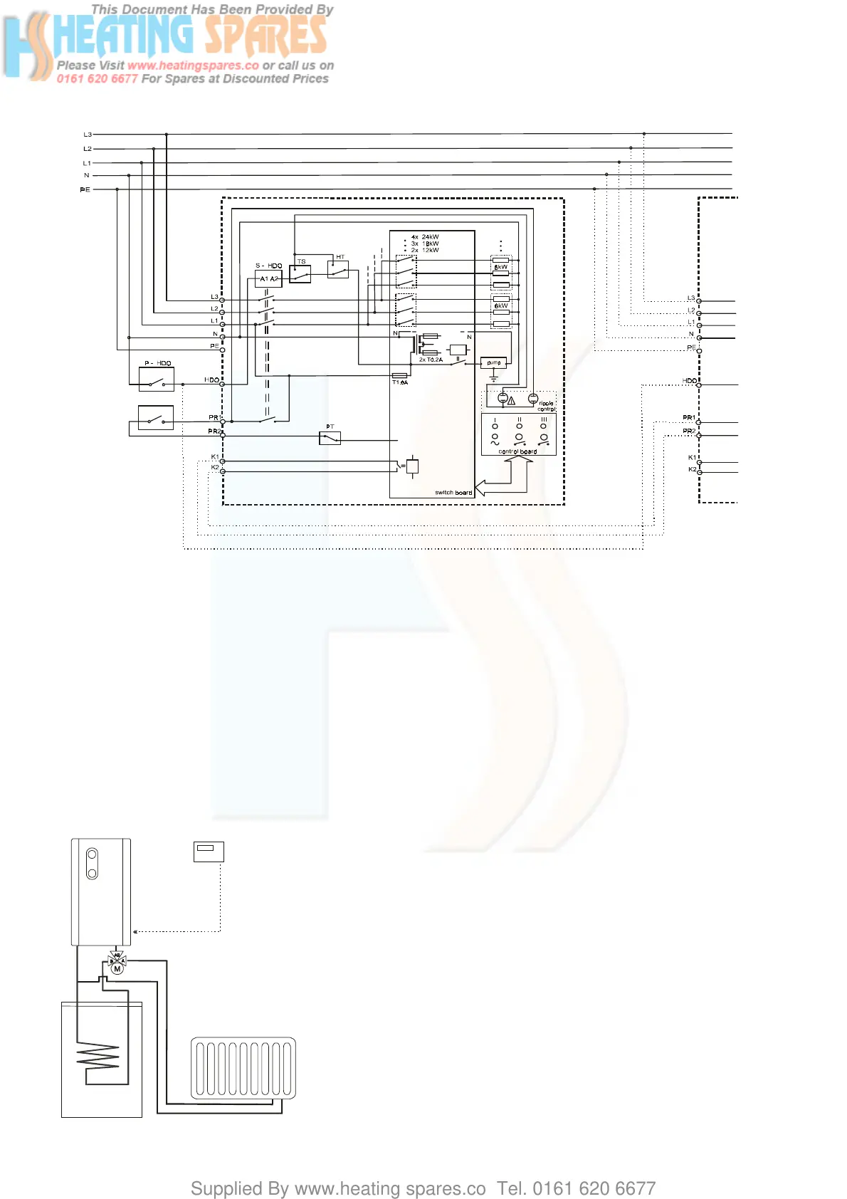
13.1. Wiring diagram of two boilers connected to cascade
TS – pressure switch 0,8 Bar
HT – over heat thermostat 100°C
PT – operating thermostat max. 85°C
PR1,PR2 – room thermostat 230 V / 0,1 A
HDO – ripple control
S-HDO – RC contactor
K1,K2 – cascade output (only 21 kW and 24 kW)
14. Interconnection the electric boiler with DHW tank
The electric boiler PROTHERM can be to add to non-direct DHW
tank PROTHERM of series B60Z, B100MS, B100Z, B200S and B200Z.
For a correct communication between the boiler and the DHW tank itś
necessary to fill following conditions which relate to a pic. on the page No.
13.
Assembly conditions:
- to a distribution a heating water into a heating system or into DHW itś
necessary to use a 3-way motor valve with donkey-switching contact (3/4”
valve with a exterior screw - No. in a order 2046, 1” valve with a interior
screw – No. in a order 2045)
- contacts of a room thermostat (PR) are played to donkey-contact W1
and W2 of the 3-way motor valve
- the room thermostat will be connect between a contact of a thermostat
of the DHW tank TB2 and a contact of a supply phase of the 3-way valve
motor
cascade
connection
PR
boiler
DHW tank